A semi-rotary mechanism with fixed shaft and belt drive

A technology of belt transmission and fixed shaft, which is applied in the field of bionic machinery, can solve the problems of poor motion stability and load-bearing capacity, poor motion stability and load-bearing capacity of the mechanism, and can only work in one direction, so as to improve work reliability and improve Carrying capacity, the effect of reducing centrifugal force

Active Publication Date: 2018-10-23
ANHUI UNIVERSITY OF TECHNOLOGY
View PDF8 Cites 0 Cited by
  • Summary
  • Abstract
  • Description
  • Claims
  • Application Information

AI Technical Summary

Problems solved by technology

Therefore, there are many moving parts in the mechanism, the moving mass is large, and the unbalanced inertial force generated is relatively large, which affects the working performance of the mechanism.
The well-known CN 102837751 A grooved shaft-type half-rotation mechanism changed the more complicated scheme of setting gear train transmission inside the pivoting arm, and proposed a half-rotation mechanism with the least parts and the simplest structure, but the motion stability and carrying capacity of the mechanism poor
The known CN105240474A crank rocker type half-rotation mechanism with one-way bearing solves the problem of poor motion stability and load-carrying capacity of the mechanism by limiting the one-way rotation of the rocker and the half-rotation rod, but increases the moving parts of the mechanism, The weight of the mechanism is relatively large, and at the same time, the steering of the input shaft is limited, and it can only work in one direction, which limits the applicability of the mechanism

Method used


Image

  • A semi-rotary mechanism with fixed shaft and belt drive
  • A semi-rotary mechanism with fixed shaft and belt drive

Examples


Embodiment Construction

[0014] The present invention will be described in detail below in conjunction with the accompanying drawings and specific embodiments, but the present invention is not limited to the following embodiments.

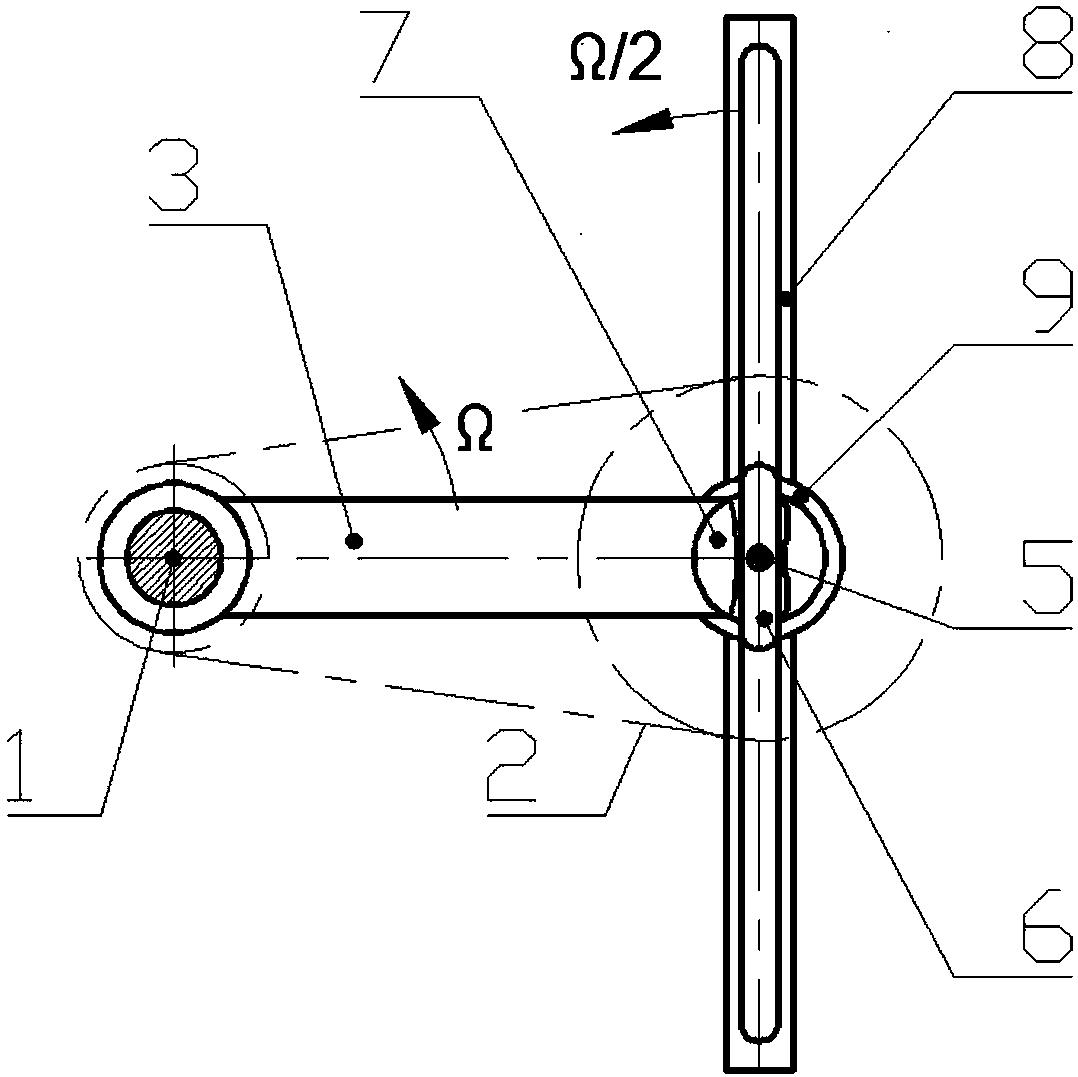
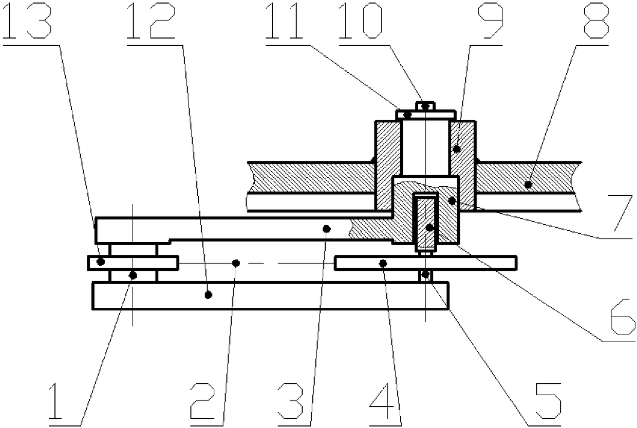
[0015] figure 1 One end of the middle crank 3 is fixedly connected with the main shaft 1, and the other end is fixedly connected with the moving shaft 7. The slide block 6 is fixedly connected with the auxiliary shaft 5, the distance from the auxiliary shaft 5 to the main shaft 1 is equal to the length of the crank 3, and the length of the slide block 6 is greater than the length of the opening groove+the thickness of the slide block 6. The middle part of the half-rotating rod 8 is fixedly connected with the axle sleeve 9, and the half-rotating rod 8 has a longitudinal chute along the axis of the rod. The length of the longitudinal chute must be greater than 4 times the length of the crank 3, and the longitudinal chute passes through The shaft sleeve 9 forms a correspondi...


PUM


Abstract

The invention provides a half-rotating mechanism driven by a fixed shaft belt and belongs to the technical field of biosimulation machines. The half-rotating mechanism comprises a main shaft, a crank, a movable shaft, a half-rotating rod, a shaft sleeve, a longitudinal sliding groove, a sliding block, an auxiliary shaft, a small driving wheel, a big driving wheel, a driving belt and a rack. The main shaft and the small driving wheel are fixedly connected, the big driving wheel and the auxiliary shaft are fixedly connected, the main shaft and the auxiliary shaft are arranged on the rack, and the driving belt is connected with the small driving wheel and the big driving wheel at the same time. One end of the crank is fixedly connected with the main shaft, and the other end of the crank is fixedly connected with the movable shaft. The movable shaft is arranged in the shaft sleeve and can rotate relative to the shaft sleeve. The shaft sleeve is fixedly connected to the middle portion of the half-rotating rod, and the longitudinal sliding groove in the axis direction of the rod is formed in the half-rotating rod. The sliding block is fixedly connected with the auxiliary shaft, and the sliding block can slide in the longitudinal sliding groove. The half-rotating mechanism overcomes the defects that in an existing half-rotating mechanism, a half-rotating rod moves unstably, the contact force of a sliding block is large, and the bearing capacity of the sliding block is small. The half-rotating mechanism can greatly improve the various mechanical properties based on the half-rotating mechanism.

Description

technical field [0001] The invention belongs to the technical field of bionic machinery, and in particular relates to a half-turn mechanism driven by a fixed shaft belt. Background technique [0002] The semi-rotary mechanism is a mechanism that can produce asymmetrical rotation and is used for animal motion bionics. It has been used to form the double blade propeller of Chinese patent CN100534858, CN104192307A a kind of imitation bird flapping wing mechanism, CN200510040830.8 rotating walking wheel and the walking mechanism of CN200910263070 double straight rod leg walking wheel, etc. In the semi-rotary mechanisms used in these projects, the asymmetrical rotation of the output member is achieved by a planetary gear drive or a chain drive placed inside the boom. Therefore, there are many moving parts of the mechanism, the mass of the movement is large, and the unbalanced inertial force generated is relatively large, which affects the working performance of the mechanism. T...

Claims


Application Information

Patent Timeline
Patent Type & Authority Patents(China)
IPC IPC(8): F16H37/12
CPCF16H37/124
Inventor 王孝义张玉华方灼明邱支振
Owner ANHUI UNIVERSITY OF TECHNOLOGY
Why Eureka
Try Eureka