
Discharging device and furnace kiln with same

A technology of discharging device and kiln, applied in the fields of waste treatment, metallurgy and chemical industry, can solve the problems of adverse effects of transportation and process treatment, easy leakage of materials, and waste materials, etc., to improve heat transfer efficiency and utilization rate, The effect of improving economic efficiency

Pending Publication Date: 2017-05-17
SHENWU TECH GRP CO LTD
View PDF0 Cites 0 Cited by
  • Summary
  • Abstract
  • Description
  • Claims
  • Application Information

AI Technical Summary

Problems solved by technology

However, the screw discharge machine has the following disadvantages: (1) the screw discharge machine relies on the rotation of the screw shaft to discharge the material, which is prone to material leakage; (2) in order to reduce the material leakage as much as possible, the speed of the screw shaft must be increased. The higher the height, the stronger the impact of the spiral blade on the material, which will easily cause the crushing of the material, which will have an adverse effect on the subsequent transportation and process treatment, and even make the material a waste; (3) the spiral blade needs to cut into the material first when pushing the material, Causes the crushing of materials, and the higher the speed, the stronger the crushing effect
(4) Heating is usually used during the process, and the size of the furnace bottom is relatively large, and the deformation of the furnace bottom will also be relatively large, so there must be enough space between the spiral blade and the furnace bottom to ensure that the spiral blade and the furnace bottom will not Scratches cause damage, however, the above-mentioned gap makes some materials remain at the bottom of the furnace and cannot be discharged, which reduces the heating efficiency of the furnace and the utilization rate of the bottom of the furnace, resulting in a lot of waste

Method used


Image

  • Discharging device and furnace kiln with same
  • Discharging device and furnace kiln with same
  • Discharging device and furnace kiln with same

Examples


Embodiment Construction

[0035] Embodiments of the present invention are described in detail below, examples of which are shown in the drawings, wherein the same or similar reference numerals designate the same or similar elements or elements having the same or similar functions throughout. The embodiments described below by referring to the figures are exemplary only for explaining the present invention and should not be construed as limiting the present invention.

[0036] In describing the present invention, it is to be understood that the terms "center", "longitudinal", "transverse", "length", "width", "thickness", "upper", "lower", "front", " Rear", "Left", "Right", "Vertical", "Horizontal", "Top", "Bottom", "Inner", "Outer", "Axial", "Radial", "Circumferential" The orientation or positional relationship indicated by etc. is based on the orientation or positional relationship shown in the drawings, which is only for the convenience of describing the present invention and simplifying the descripti...


PUM


Abstract

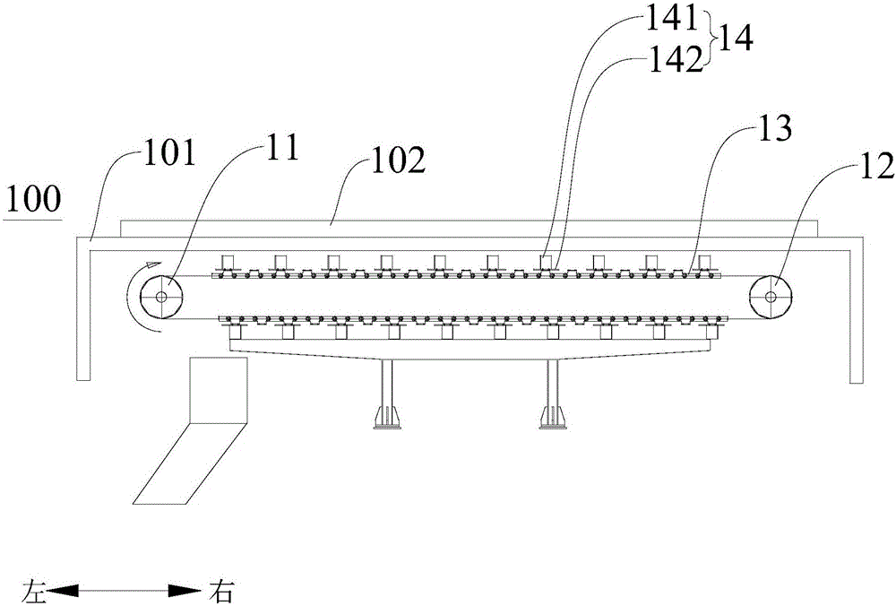
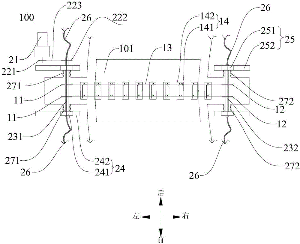
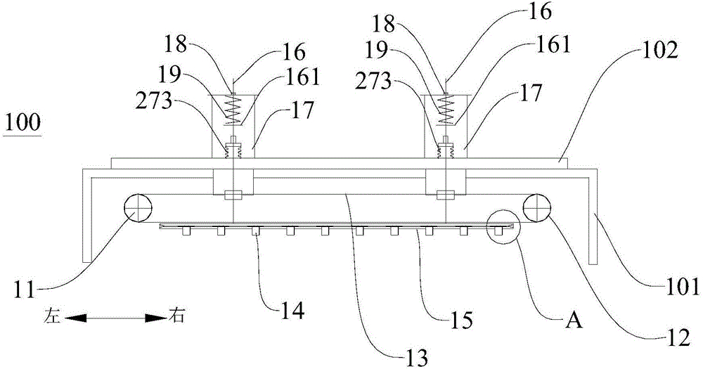
The invention discloses a discharging device and a furnace kiln with the same. The discharging device comprises first scrapping plate chain wheels, second scrapping plate chain wheels, scrapping plate chains, a driving assembly and a plurality of scrapping plates, and the second scrapping plate chain wheels are spaced from the first scrapping plate chain wheels in the left-right direction. The scrapping plate chains are formed to be annular and arranged outside the first scrapping plate chain wheels and the second scrapping plate chain wheels in a wound mode. The driving assembly is connected with the first scrapping plate chain wheels and used for driving the first scrapping plate chain wheels to rotate so that the scrapping plate chains can be driven to rotate. The multiple scrapping plates are arranged in a spaced mode in the circumferential directions of the scrapping plate chains, and the scrapping plates on the lower portions of the scrapping plate chains can move up and down. According to the discharging device, the positions of the scrapping plates on the lower portions of the scrapping plate chains can be flexibly adjusted so that the scrapping plates on the lower portions of the scrapping plate chains can be adaptable to deformation of the furnace bottom and keep making contact with the furnace bottom, thus the effect that materials at the furnace bottom are completely scrapped is ensured, heat transfer efficiency is improved, the utilization ratio of the furnace kiln using the discharging device is increased, and the economic benefits of the furnace kiln are greatly improved.

Description

technical field [0001] The invention relates to the technical fields of metallurgy, chemical industry and garbage treatment, in particular to a discharging device and a kiln with the same. Background technique [0002] In related technologies, industrial furnaces such as annular furnaces and rotary hearth furnaces are widely used in the fields of metallurgy, chemical industry, and garbage disposal to process bulk materials. The discharge device used is one of the key equipment. The discharge device Good working performance and discharge effect are important guarantees for normal, safe and efficient production. [0003] The discharge device of the industrial furnace in the related art is usually a screw discharge machine, mainly through the rotation of the screw shaft, the material is pushed into the discharge hopper by the screw blade to realize the discharge. However, the screw discharge machine has the following disadvantages: (1) the screw discharge machine relies on the...

Claims


Application Information

Patent Timeline
IPC IPC(8): F27D3/00
CPCF27D3/00F27D2003/0066
Inventor 米海亮安建广吴道洪
Owner SHENWU TECH GRP CO LTD
Learn More