Air-cooled heat pipe radiator with upright heat-conducting surfaces
A heat pipe radiator, heat conduction surface technology, applied in indirect heat exchangers, lighting and heating equipment, etc., can solve the problem of low efficiency
- Summary
- Abstract
- Description
- Claims
- Application Information
AI Technical Summary
Problems solved by technology
Method used
Image
Examples
Embodiment 1
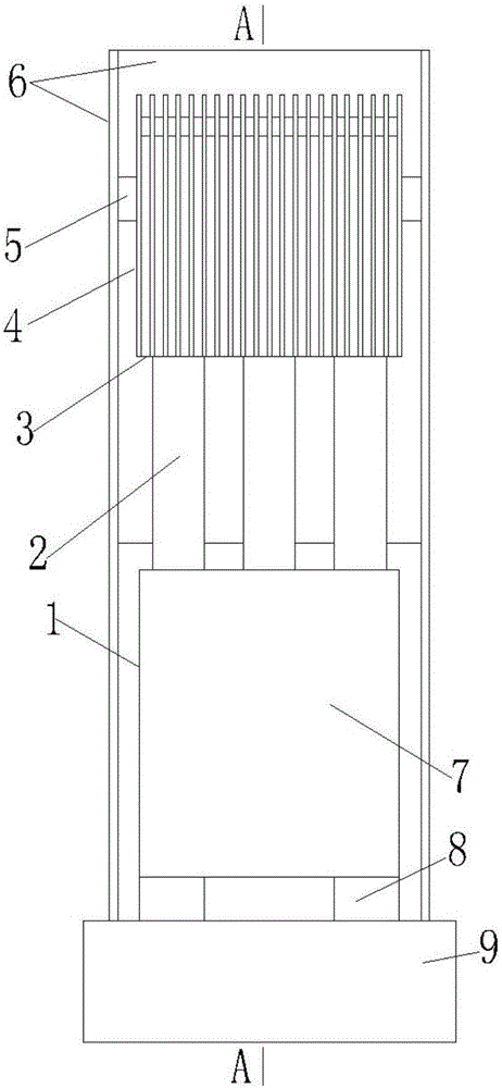
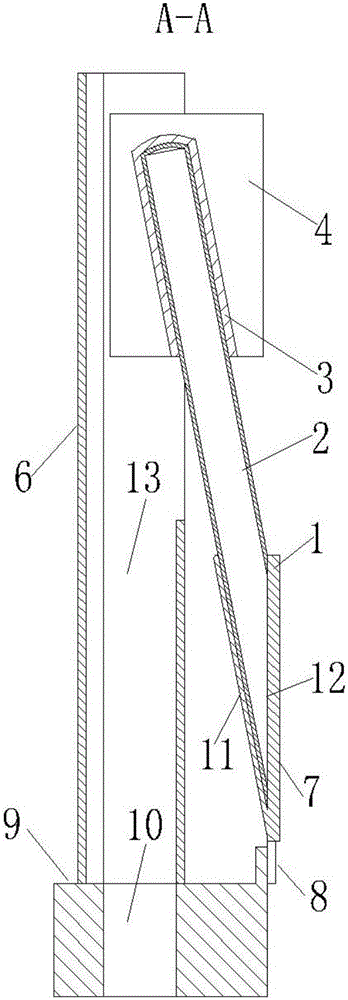
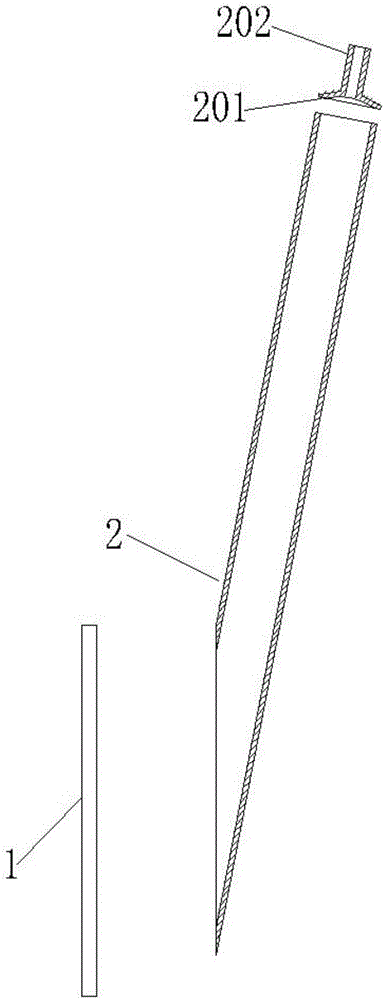
[0022] Example 1, Figure 8 is a schematic diagram of embodiment 1, wherein the radiator assembly 32 includes figure 1 or figure 2 The combination of all parts in the circuit board 34 is vertically installed (other components on it are omitted and not shown), the area of the heat conduction surface of the heat conduction block 1 of the evaporation section in the contact direction with the working object ≥ the area of the heat dissipation surface 33 of the heating element, And keep the whole area in close contact, and apply heat-conducting silicone grease on the contact surface; multiple identical circuit boards 34 are vertically parallel installed (only 2 groups are drawn in the figure, and the rest are omitted), and the space between the circuit boards is limited, so The fan 30 is installed in the base 36, blows upward, and the air flow is guided through the channel formed by the fan air duct 31, the relay air duct 10, and the upper air supply duct 13, and is concentrat...
Embodiment 2
[0023] Example 2, Figure 9 is a schematic diagram of embodiment 2, wherein the radiator assembly 32 is composed of figure 1 or figure 2 The combination of all parts in the circuit board 34 is vertically installed (other components on it are omitted and not shown), the area of the heat conduction surface of the heat conduction block 1 of the evaporation section in the contact direction with the working object ≥ the area of the heat dissipation surface 33 of the heating element, And keep the whole area in close contact, and apply thermal conductive silicone grease on the contact surface; multiple identical circuit boards 34 are vertically parallel installed (only 2 groups are drawn in the figure, and the rest are omitted), the space between the circuit boards is limited, but There are also many parts in the base 36, fan 30 cannot be installed, so adopt the mode of drafting from above to carry out air cooling, increase support frame and add vent 37, blower fan 38, air outl...
Embodiment 3
[0024] Example 3, Figure 10 is a schematic diagram of embodiment 3, wherein the radiator assembly 32 includes figure 1 or figure 2 The combination of all parts in the circuit board 34 is vertically installed (other components on it are omitted and not shown), the area of the heat conduction surface of the heat conduction block 1 of the evaporation section in the contact direction with the working object ≥ the area of the heat dissipation surface 33 of the heating element, And keep the whole area in close contact, and apply heat-conducting silicone grease on the contact surface; multiple identical circuit boards 34 are vertically parallel installed (only 2 groups are drawn in the figure, and the rest are omitted), the space between the circuit boards is limited, due to The heat of the heating element is relatively large, and there is space in the base 36 to install the blower fan 30. Therefore, the mode of drafting from the top and the coordinated mode of blasting from t...
PUM
 Abstract
Description
Claims
Application Information
 - R&D
- Intellectual Property
- Life Sciences
- Materials
- Tech Scout
- Unparalleled Data Quality
- Higher Quality Content
- 60% Fewer Hallucinations
Browse by: Latest US Patents, China's latest patents, Technical Efficacy Thesaurus, Application Domain, Technology Topic, Popular Technical Reports.
© 2025 PatSnap. All rights reserved.Legal|Privacy policy|Modern Slavery Act Transparency Statement|Sitemap|About US| Contact US: help@patsnap.com


