Cutter and workpiece instantaneous contact contour extraction method during five-axis side-milling machining

A technology of instantaneous contact and contour extraction, which is applied in the field of mechanical machining, can solve the problems of narrow application range and low efficiency, and achieve the effect of avoiding secondary development and taking into account calculation efficiency

Active Publication Date: 2017-05-17
TSINGHUA UNIV
View PDF3 Cites 7 Cited by
  • Summary
  • Abstract
  • Description
  • Claims
  • Application Information

AI Technical Summary

Problems solved by technology

[0005] In order to solve the problems of narrow application range and low efficiency of the existing method for judging the instantaneous contact area between the milling cutter and the workpiece in the five-axis side milling process, the present invention provides a method for extracting the instantaneous contact contour between the tool and the workpiece in the five-axis side milling process

Method used


Image

  • Cutter and workpiece instantaneous contact contour extraction method during five-axis side-milling machining
  • Cutter and workpiece instantaneous contact contour extraction method during five-axis side-milling machining
  • Cutter and workpiece instantaneous contact contour extraction method during five-axis side-milling machining

Examples


Embodiment 1

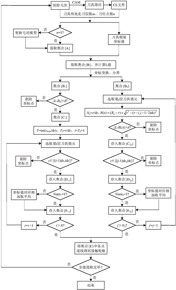
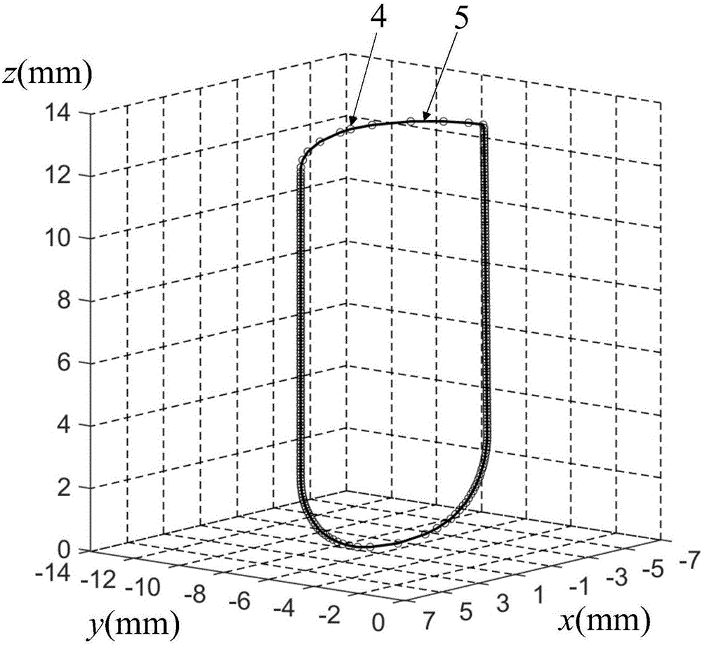
[0057] Example 1: Calculation of the instantaneous contact contour between the round nose end mill and the workpiece at the first milling layer and the 270th tool position during the side milling process of the S-shaped test piece. The calculation process is as follows figure 1 shown.

[0058] 1) The given initial condition information is as follows:

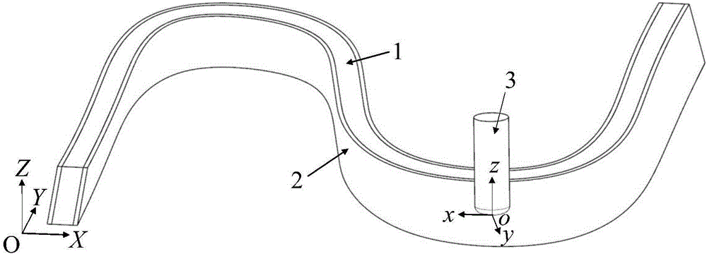
[0059] The target part processed in this embodiment is a 10 mm thick S-shaped test piece. The initial blank is obtained by symmetrically adding 2 mm thick layers to be removed on both sides of the target part. With any point on the bottom surface of the blank as the origin, the processing coordinate system O-XYZ is established. , the processing tool is a round nose end mill, and the tool radius R 0 = 8mm, tool arc radius r = 3mm, the overall height of the blank is 30mm, and it is processed in 3 layers;

[0060] The tool path of each layer of milling is automatically generated by the UG software in CAM, and the cutting position...

Embodiment 2

[0075] Example 2: Calculation of the instantaneous contact contour between the round nose end mill and the workpiece at the second milling layer and the 270th tool position during the side milling process of the S-shaped test piece. The calculation process is as follows figure 1 shown.

[0076] 1) The given initial condition information is as follows:

[0077] The target part processed in this embodiment is a 10mm thick S-shaped test piece. The initial blank is obtained by symmetrically adding 2mm thick layers to be removed on both sides of the target part. The processing coordinate system is represented by O-XYZ, and the processing tool is a round nose milling cutter. , tool radius R 0 = 8mm, tool arc radius r = 3mm, the overall height of the blank is 30mm, and it is processed in 3 layers;

[0078] The tool path of each layer of milling is automatically generated by the UG software in CAM, and the cutting position file including the position of the tool nose point, the tool...


PUM


Abstract

The invention discloses a cutter and workpiece instantaneous contact contour extraction method during five-axis side-milling machining and belongs to the technical field of machining. The method includes generating a cutting position file through CAM (computer-aided manufacturing) software and updating a workblank according to the cutting layer number; extracting workblank surface coordinate points and judging a point set area suitably used for a current cutter position according to given cutter position point information; scattering a cutter axially into a plurality of cutter microelements, traversing every microelement by taking cutter axis perpendicular length and a cutter microelement axial range as limiting conditions so as to extract the coordinate points nearby a cutter contour line; connecting the coordinate points to obtain the contact contour between the cutter and a workpiece at the designated cutter position point during layered milling. The cutter and workpiece instantaneous contact contour extraction method during five-axis side-milling machining has the advantage that complex curved surface descriptions and a secondary software development process are avoided, and accordingly the method is applicable to judgment of the cutter and workpiece instantaneous contact area during five-axis side-milling machining of a flat-end milling cutter, a round-nose end milling cutter and a ball-nose end milling cutter.

Description

technical field [0001] The invention relates to a method for extracting the instantaneous contact contour between a tool and a workpiece during a five-axis side milling process, and is particularly suitable for the five-axis side milling process of a flat end mill, a round nose end mill and a ball end mill. The invention relates to the determination of the instantaneous contact area of ​​a workpiece, which belongs to the technical field of mechanical machining. Background technique [0002] Five-axis side milling is a typical line contact processing method. It uses the side edge of the rotary tool to mill the surface of the part to be processed. It has the advantages of high processing efficiency and good cutting conditions. It has been widely used in aerospace, automobile, mold and other industries. widely used. In order to solve the problems of machining deformation, machining chatter and tool wear in the process of five-axis side milling, and ensure the quality of parts ...

Claims


Application Information

Patent Timeline
Patent Type & Authority Applications(China)
IPC IPC(8): G05B19/4097
CPCG05B19/4097G05B2219/34098
Inventor 王立平佀昊
Owner TSINGHUA UNIV
Why Eureka
Try Eureka