
Voltage transformer with elbow plug

A technology for voltage transformers and plugs is applied in the field of transformers, which can solve the problems of epoxy resin damage of transformers, inability to be popularized and applied, and scrapped products, etc., and achieve the advantages of miniaturization design, guarantee of electrical performance, and convenient installation and maintenance. Effect

Active Publication Date: 2017-05-17
ZHEJIANG HORIZON INSTR TRANSFORMERS
View PDF7 Cites 3 Cited by
  • Summary
  • Abstract
  • Description
  • Claims
  • Application Information

AI Technical Summary

Problems solved by technology

This structure has the following problems: First, because the product is usually installed at the bottom of the switch cabinet, the high-voltage cable is connected to the switch cabinet through the cable trench, and the bending radius of the cable is extremely small. When opening the elbow-shaped cable plug, the high-voltage special fusion tube must be pulled out together with the plug, which is very difficult to plug in and out, which will easily cause damage to the epoxy resin at the primary fusion tube port of the transformer, and even lead to product scrap
However, in the actual promotion, since the cable socket and the elbow cable plug are usually located at the door end of the switch cabinet, the corresponding rear end is the back panel of the switch cabinet, which is in a closed state. There is a technical solution for replacing and installing the fuse at the rear end, which is useless in the application. When replacing and installing the fuse, it is still necessary to remove the elbow cable head to replace the fuse. Therefore, this patented technical solution cannot get promoted

Method used


Image

  • Voltage transformer with elbow plug
  • Voltage transformer with elbow plug
  • Voltage transformer with elbow plug

Examples


Embodiment Construction

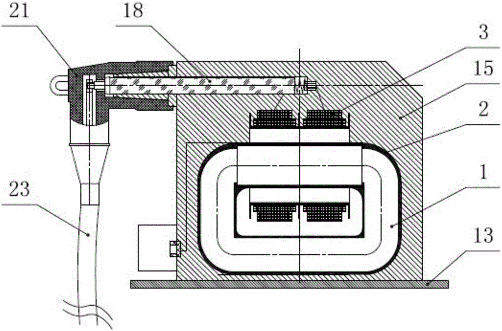
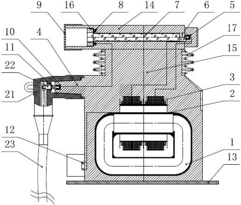
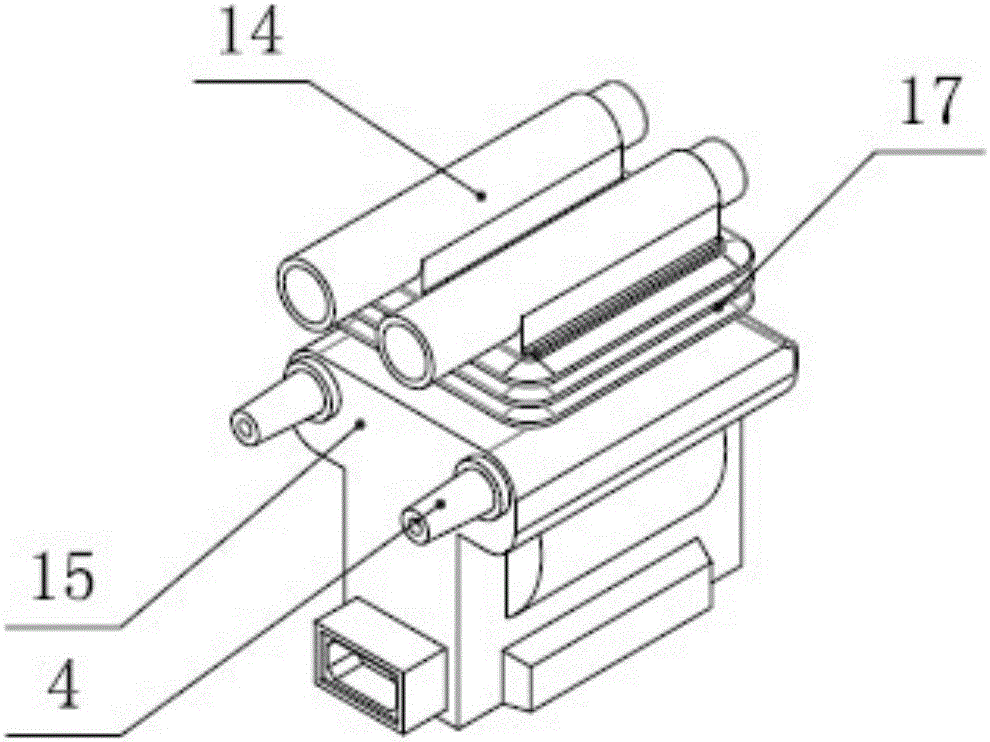
[0019] Please refer to figure 2 and image 3 As shown in the figure, a voltage transformer with an elbow plug is a single mutual inductor structure, the A and B ends of the primary winding 3 are connected to the high-voltage line, and the secondary winding 2 directly outputs the voltage through the electromagnetic induction of the annular iron core 1. It is used for measurement and control of the secondary system. Its structure includes epoxy resin casting main body 15, elbow cable plug 21, fuse 7 and epoxy resin casting integrated primary winding 3, secondary winding 2, iron core 1, cable socket 4, epoxy resin casting A bottom plate 13 is installed under the main body 15, and a secondary terminal 12 is provided at the lower part of the epoxy resin cast main body 15. The secondary terminal 12 is connected to the secondary winding 2, and the bottom end of the elbow-shaped cable plug 21 is connected to a high-voltage cable 23. The high-voltage cable 23 is introduced into the ...


PUM


Abstract

The invention provides a voltage transformer with an elbow plug. An independent fuse seat is integrally arranged at the top of a cable socket; a fuse cavity accommodating a fuse protector is arranged in the fuse seat; an open end of the fuse cavity and the cable socket are located at the same side; an embedded part is arranged at the tail end of the fuse cavity; a detachable fixed plate is arranged at the open end of the fuse cavity; the fuse protector is arranged between the embedded part and the fixed plate; one end of the fuse protector is propped against a spring; the fuse protector is electrically connected with the embedded part and the fixed plate; a primary terminal is embedded into the cable socket; a primary conductive rod is arranged on an elbow cable plug; and when the elbow cable plug is inserted into the cable socket, the primary conductive rod is electrically connected with the primary terminal through a pressure spring and the primary terminal is connected with a primary coil through the fuse protector of the fuse cavity. When the fuse protector is replaced, the complicated process of disassembling and assembling the plug is avoided, the operation is simple and convenient, the work efficiency is improved, a lot of replacement time is shortened and the voltage transformer has very high popularization and application value.

Description

technical field [0001] The invention belongs to the technical field of transformers, and in particular relates to a voltage transformer. Background technique [0002] The existing voltage transformer with an elbow plug has its own high-voltage fuse, and the elbow plug plus a high-voltage cable can well insulate the high-voltage end of the voltage. Elbow-type cable plugs are installed on the insulating shell, which changes the traditional voltage primary outlet, and the insulating shell is built with a replaceable fuse, which does not need to be installed separately, reducing the space occupied by the voltage transformer. Therefore, This product has been widely used. During the long-term operation of the voltage transformer, due to the fluctuation or abnormal operation of the power grid, the fuse of the voltage transformer will be blown, and the maintenance personnel need to replace the fuse immediately. Due to the miniaturization of electrical switches and other reasons, p...

Claims


Application Information

Patent Timeline
Patent Type & Authority Applications(China)
IPC IPC(8): H01F38/26H01F27/40H01F27/29
CPCH01F27/292H01F27/402H01F38/26
Inventor 祝顺峰毛培民
Owner ZHEJIANG HORIZON INSTR TRANSFORMERS
Learn More