Liquid injection equipment and method

A liquid injection and equipment technology, applied in electrical components, circuits, battery pack components, etc., can solve the problems of cell fire, pollution, and sealant nail contamination with electrolyte, etc., to reduce the probability of fire and improve the yield. Effect

Pending Publication Date: 2017-05-17
CONTEMPORARY AMPEREX TECH CO
View PDF7 Cites 3 Cited by
  • Summary
  • Abstract
  • Description
  • Claims
  • Application Information

AI Technical Summary

Problems solved by technology

[0004] However, in the existing liquid injection equipment, since the sealing rubber nail needs to pass through the liquid injection pipe when it is pressed into the liquid injection hole, and part of the electrolyte will remain in the liquid injection pipe after the liquid injection is completed, the sealin

Method used


Image

  • Liquid injection equipment and method
  • Liquid injection equipment and method
  • Liquid injection equipment and method

Examples


Embodiment Construction

[0050] The present application will be described in further detail below through specific embodiments and in conjunction with the accompanying drawings.

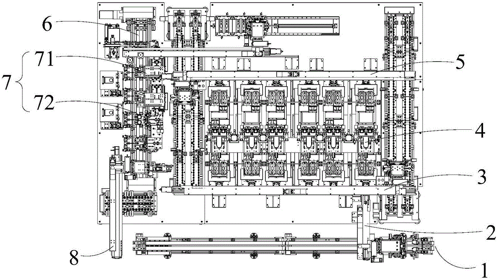
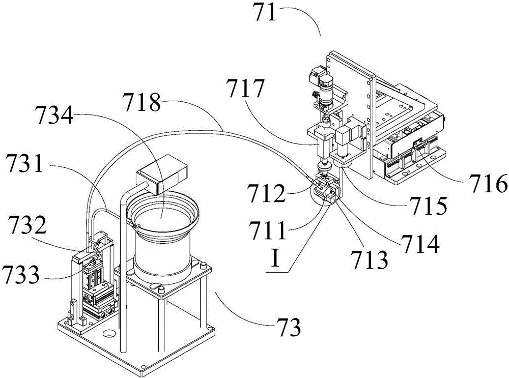
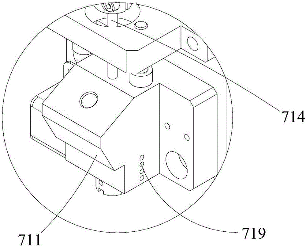
[0051] Such as Figure 1-4 As shown, the embodiment of the present application provides a liquid injection device, which is used for secondary liquid injection of the battery cell and pressing a sealing glue nail into the liquid injection hole of the battery cell. The liquid injection equipment includes a liquid injection filling helium module 4 and a nailing module 7 . The liquid injection helium module 4 and the nailing module 7 are arranged at different stations along the conveying direction (that is, the conveying direction of the conveyor belt 6), that is, the liquid injecting helium module 4 is located at the liquid injection station, and the nailing module 7 is located at the nailing station. Since the liquid injection process of the battery cell is not at the same station as the process of pressing the sealant nail,...


PUM


Abstract

The invention relates to the technical field of production of an energy storage device, in particular to liquid injection equipment and method. The liquid injection equipment comprises a liquid injection helium-inflated module and a nailing module, wherein the liquid injection helium-inflated module and the nailing module are arranged at different stations along a transmission direction, the liquid injection helium-inflated module is used for injecting a liquid into a battery cell and inflating the battery cell with an inert gas, and the nailing module is used for pressing a sealant nail into a liquid injection hole of the battery cell so that the liquid injection hole is sealed by the sealant nail. By the liquid injection equipment, the liquid injection process and the sealant nail pressing process are respectively operated at different stations, the sealant nail directly enters the liquid injection hole and does not need to pass through a liquid injection pipe, so that the sealant nail is prevented from being polluted by an electrolyte in the liquid injection pipe, the defects such as a pinhole, an explosion point, a step and a pit occurring during the subsequent laser welding process of the sealant nail can be reduced, the probability of causing the battery cell to be on fire is reduced, and the finished rate of the battery cell is improved.

Description

technical field [0001] The present application relates to the technical field of production of energy storage devices, in particular to a liquid injection device and method. Background technique [0002] With the development of modern society, cars have already become the most important tool in human life. The emergence of new energy vehicles has greatly reduced exhaust emissions and can effectively protect the environment. As a kind of power source of new energy vehicles, batteries have been widely welcomed in the automotive market. In the production process of the battery cell, including the liquid injection process and the sealing welding process, due to the time difference between the liquid injection process and the sealing welding process, in order to prevent the expansion of the battery due to gas production between the two processes, usually during the liquid injection Finally, press in the sealant nail to keep a slight negative pressure inside the cell. [0003] ...

Claims


Application Information

Patent Timeline
IPC IPC(8): H01M2/36
CPCH01M50/60H01M50/636Y02E60/10
Inventor 官锋
Owner CONTEMPORARY AMPEREX TECH CO
Why Eureka
Try Eureka