Bandwidth adjustable n*3 lattice type vibration energy collector based on modal separation technology
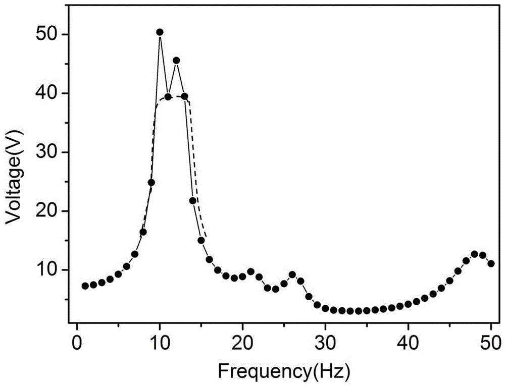
A vibration energy harvesting and mode separation technology, which is applied to piezoelectric effect/electrostrictive or magnetostrictive motors, generators/motors, electrical components, etc., can solve the problems of narrow operating frequency band, low energy conversion efficiency, and output Low power and other issues, to achieve the effect of widening the low frequency band
- Summary
- Abstract
- Description
- Claims
- Application Information
AI Technical Summary
Problems solved by technology
Method used
Image
Examples
Embodiment 1
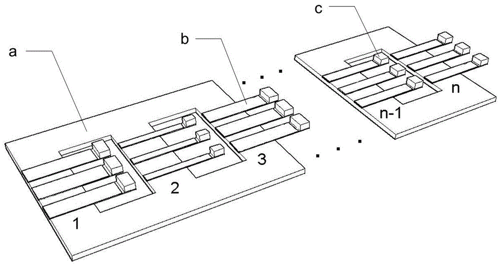
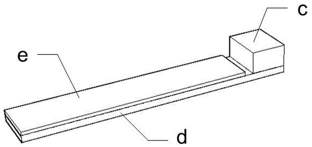
[0021] The invention comprises a flexible frame main beam structure a, a piezoelectric cantilever beam b and a quality block c, the flexible frame main beam structure a is a rectangular frame structure, and a hollow rectangular hole is opened in the center; one end of the piezoelectric cantilever beam b is pasted and fixed On the upper surface of the main beam structure a of the flexible frame, the other end is suspended in the air, the suspended length of the piezoelectric cantilever b is less than the width of the rectangular hole, and the mass c is attached to the suspended end of the piezoelectric cantilever b; the six piezoelectric cantilever beams b (n=2) are arranged at equal intervals along the same direction on both sides of the rectangular hole.
[0022] The main beam structure a of the flexible frame is made of PDMS material, and the outer sides of the two sides of the frame parallel to the piezoelectric cantilever beam b are fixed.
[0023] The piezoelectric cantil...
Embodiment 2
[0026] The invention includes a flexible frame main beam structure a, a piezoelectric cantilever beam b and a quality block c, the flexible frame main beam structure a is a rectangular frame structure, and two hollow rectangular holes are opened on the rectangular structure; the piezoelectric cantilever beam b One end is pasted and fixed on the upper surface of the main beam structure a of the flexible frame, and the other end is suspended in the air. The suspended length of the piezoelectric cantilever b is less than the width of the rectangular hole, and the mass c is attached to the suspended end of the piezoelectric cantilever b; Electric cantilever beams b (n=3) are arranged at equal intervals along the same direction on both sides of the two rectangular holes.
[0027] The main beam structure a of the flexible frame is made of PDMS material, and the outer sides of the two sides of the frame parallel to the piezoelectric cantilever beam b are fixed.
[0028]The piezoelect...
Embodiment 3
[0031] The invention includes a flexible frame main beam structure a, a piezoelectric cantilever beam b and a quality block c, the flexible frame main beam structure a is a rectangular frame structure, and four hollow rectangular holes are opened on the rectangular structure; the piezoelectric cantilever beam b One end is pasted and fixed on the upper surface of the main beam structure a of the flexible frame, and the other end is suspended in the air. The suspended length of the piezoelectric cantilever b is less than the width of the rectangular hole, and the quality block c is adhered to the suspended end of the piezoelectric cantilever b; fifteen pieces Piezoelectric cantilever beams b (n=5) are arranged at equal intervals along the same direction on both sides of the four rectangular holes.
[0032] The main beam structure a of the flexible frame is made of PDMS material, and the outer sides of the two sides of the frame parallel to the piezoelectric cantilever beam b are ...
PUM
 Abstract
Description
Claims
Application Information
 - R&D
- Intellectual Property
- Life Sciences
- Materials
- Tech Scout
- Unparalleled Data Quality
- Higher Quality Content
- 60% Fewer Hallucinations
Browse by: Latest US Patents, China's latest patents, Technical Efficacy Thesaurus, Application Domain, Technology Topic, Popular Technical Reports.
© 2025 PatSnap. All rights reserved.Legal|Privacy policy|Modern Slavery Act Transparency Statement|Sitemap|About US| Contact US: help@patsnap.com


