Hydraulic pump unit and method of assembling a hydraulic pump unit

A hydraulic pump, hydraulic technology, applied in the direction of pump components, components of pumping devices for elastic fluid, fluid pressure actuators, etc., can solve problems such as drilling failures, operation failures, etc., to achieve easy handling and reduce complexity permanent, easy-to-manufacture effects

Active Publication Date: 2019-05-10
北美动力派克公司
View PDF4 Cites 0 Cited by
  • Summary
  • Abstract
  • Description
  • Claims
  • Application Information

AI Technical Summary

Problems solved by technology

Further, contaminated boreholes lead to failure
Drilled boreholes can include small metal fragments which can lead to operational failure

Method used


Image

  • Hydraulic pump unit and method of assembling a hydraulic pump unit
  • Hydraulic pump unit and method of assembling a hydraulic pump unit
  • Hydraulic pump unit and method of assembling a hydraulic pump unit

Examples


Embodiment Construction

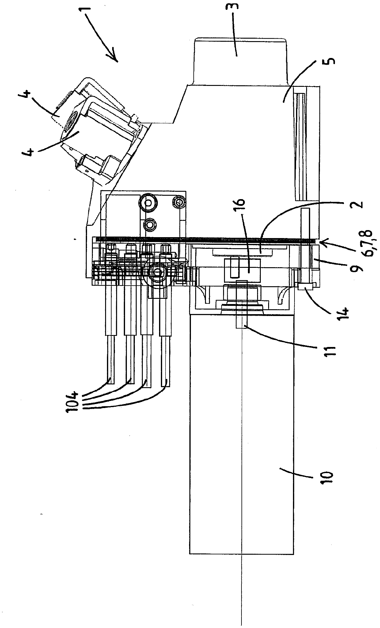
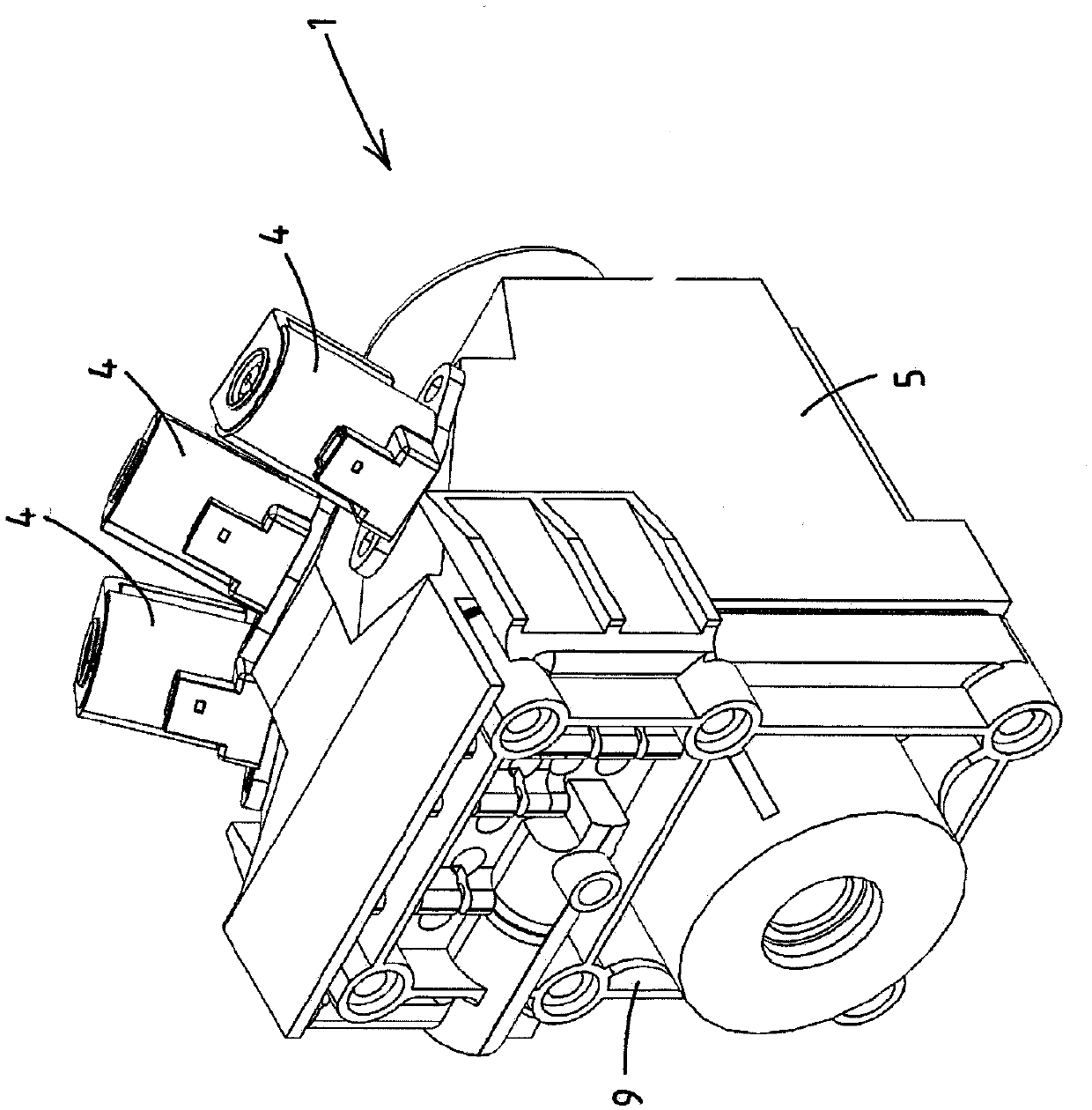
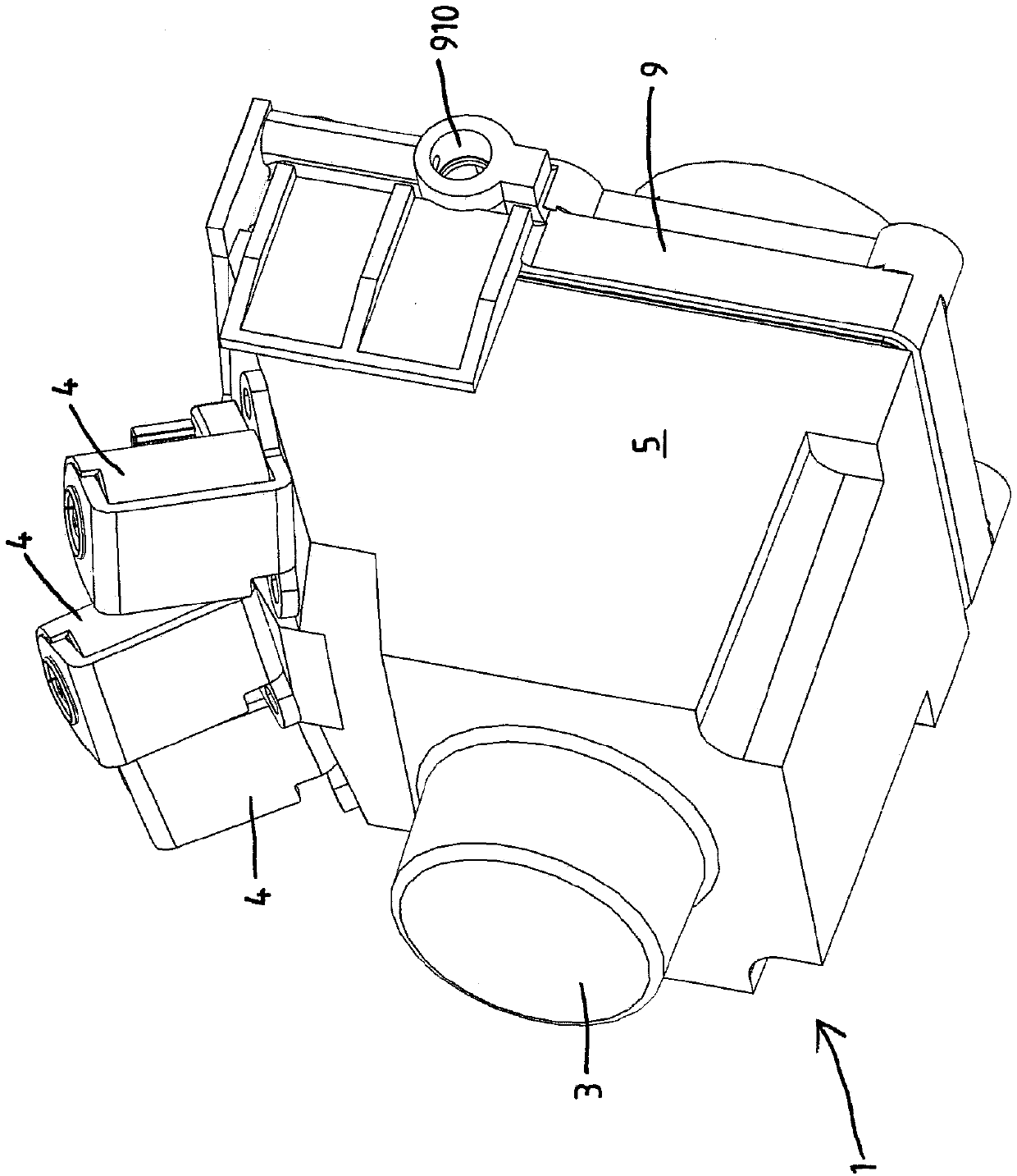
[0161] The hydraulic pump unit 1 is configured for supplying pressurized hydraulic fluid to a set of hydraulic actuators at a pressure of eg several tens of bar or even over 100 bar.

[0162] see Figure 26 , 27 , the set of hydraulic actuators includes a plurality of actuators, wherein a first actuator can be arranged to move independently of a second actuator, for example one actuator operates one element of a convertible roof system, the other An actuator operates another element of the system. The actuators herein may also be a pair of parallel actuators operating synchronously. For example, a first actuator can move with a different stroke or speed than a second actuator at the same moment.

[0163] The hydraulic pump unit 1 comprises a main body 5, a rotary drive shaft operated pump 2, a drive motor 10 and a reservoir 3 for hydraulic fluid. The end body 9 is provided with a plurality of line connectors 99 for connecting the actuator line 104 to the unit 1, such as a ...


PUM


Abstract

A hydraulic pump unit (1) comprising a pump (2), a reservoir (3), a plurality of line connectors (99) and at least one valve seat (40) and a main body (5) comprising pipes A channel system (50) at a pipe end (502) defining a plurality of ports (52) in a common port face (51). The port face (51) of the main body (5) is the plane of the outer surface of the main body (5). The pump unit comprises a functional plate (6) comprising grooved passages (60). The functional plate (6) is placed to the port face (51) such that the slotted passage (60) cooperates with at least two ports (52) to define a flow path between these ports (52). The end body (9) sandwiches the functional plate (6) between the port face (51) of the body (5) and the end body (9) itself.

Description

technical field [0001] The invention relates to a hydraulic pump unit. The hydraulic pump unit is configured to supply pressurized hydraulic fluid to a set of hydraulic actuators. In particular, the set of hydraulic actuators may comprise a plurality of actuators, wherein a first actuator is to move independently of a second actuator. [0002] The hydraulic pump unit comprises a pump, a reservoir for hydraulic fluid and a plurality of lines for coupling the set of hydraulic actuators to the pump unit via actuator lines, for example via flexible hydraulic hoses Connector. The pump unit has at least one valve seat which allows installing an electrically operated valve or a valve for controlling the flow of hydraulic fluid, for example a directional valve. Further, the hydraulic pump unit comprises a main body comprising a channel system for the hydraulic fluid. The channel system comprises a plurality of conduits interconnecting the pump, the reservoir and the at least one v...

Claims


Application Information

Patent Timeline
Patent Type & Authority Patents(China)
IPC IPC(8): F04B53/16
CPCF04B53/16F01C21/007F04B39/123F04C15/06F15B21/003
Inventor 马塞尔·格拉尔杜斯·玛丽亚·尼乌文赫伊斯罗伯图斯·尤斯蒂努斯·斯特格曼丹尼斯·哈尔布林克约翰尼·安东尼斯·詹考伯斯·维格曼斯
Owner 北美动力派克公司
Why Eureka
Try Eureka