Heat exchanger

A technology for heat exchangers and radiators, applied in heat exchange equipment, indirect heat exchangers, heat exchanger types, etc., to solve problems such as large bending stiffness, excessive use of materials, and material waste

Inactive Publication Date: 2017-05-17
MAHLE INT GMBH
View PDF6 Cites 0 Cited by
  • Summary
  • Abstract
  • Description
  • Claims
  • Application Information

AI Technical Summary

Problems solved by technology

Side pieces consisting of a single piece, for example by sheet metal stamping, are designed to have the same wall thickness over their entire length, which occasionally leads to unnecessary use of excess material in areas where high strength or bending stiffness values ​​are not required
This is especially true in the central area, however, greater bending stiffness is required in the longitudinal end areas of the corresponding side parts
Therefore, a one-piece side piece must be constructed by stiffening over its entire length or only locally introducing due stiffness, resulting in more material being wasted in areas that are not stiffened

Method used


Image

  • Heat exchanger
  • Heat exchanger
  • Heat exchanger

Examples


Embodiment Construction

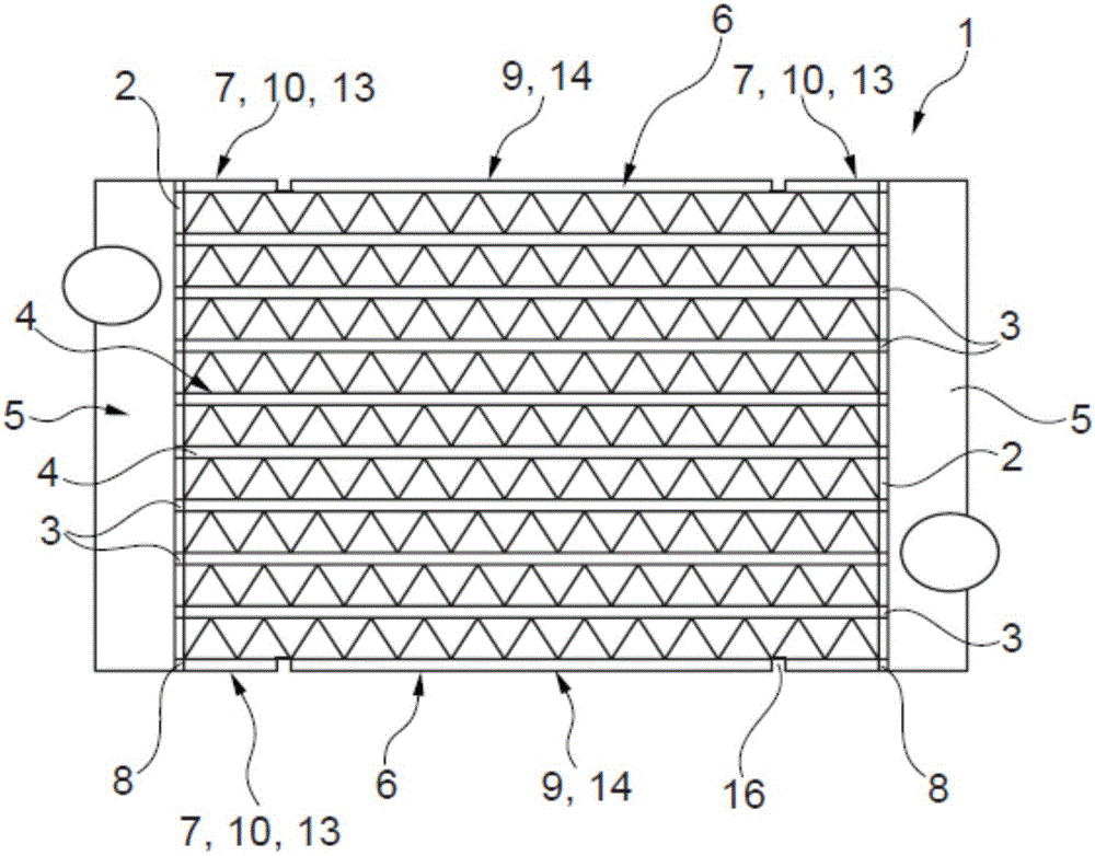
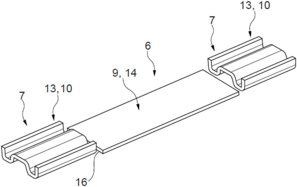
[0021] according to figure 1 A heat exchanger 1 according to the invention, which can be realized, for example, as an intercooler, comprises two floor plates 2 each having a channel 3 , for example for receiving the longitudinal end regions of fluid-conducting tubes 4 , flat tubes. The floor 2 is connected to a plenum 5 to form a collector, eg for coolant. The respective longitudinal end regions 7 of the two side parts 6 are accommodated at least partially in a channel 8 at the end of the associated floor 2 , wherein the channel 8 is likewise formed at the end by the channel 3 provided for the pipe 4 . The side pieces 6 can pass partially or all the way through the channel 8 , but do not have to. Alternatively, of course, they can also be joined to the floor 2 in some other way, for example by soldering, welding or the like.

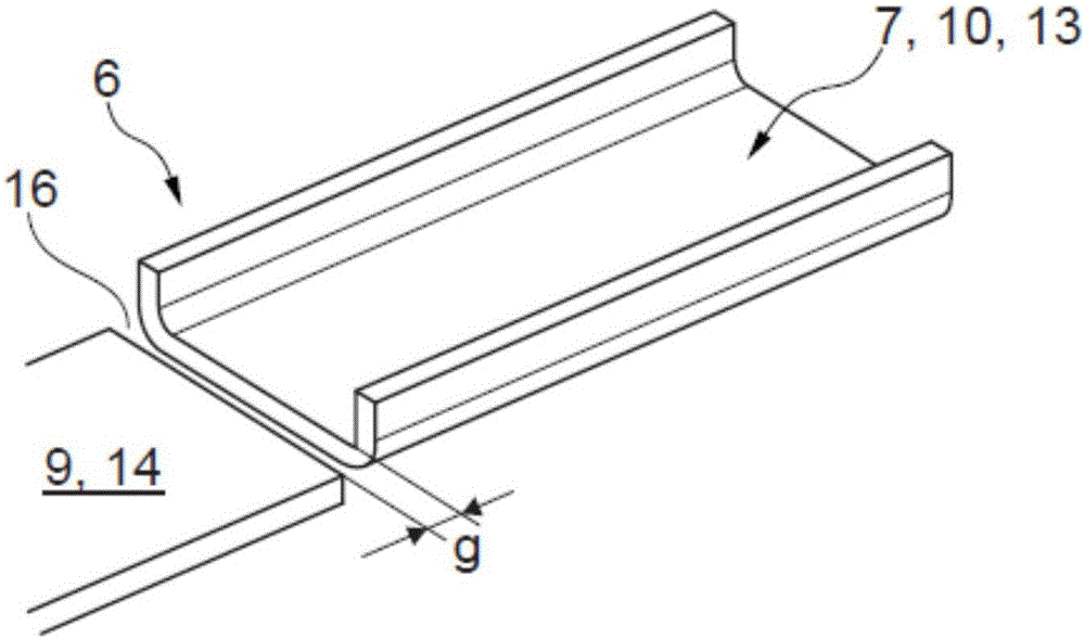
[0022] Now, in order to be able to produce a side part 6 which not only meets the more demanding bending stiffness requirements present in the longitu...


PUM


Abstract

The invention relates to a heat exchanger (1), in particular an intercooler or a coolant radiator, comprising two floors (2), each of which has passages (3) for accommodating the longitudinal end regions of fluid-conducting tubes (4), at least one side part (6), one longitudinal end region (7) of which is at least partially accommodated in a passage (8) at the end of the associated floor (2) or adjoins the floor (2). A fundamental feature of the invention is that the side part (6) has at least two segments (9,10) with differing cross-sections.

Description

technical field [0001] The invention relates to a heat exchanger, in particular an intercooler or a coolant radiator, according to the preamble of claim 1 . The invention further relates to side pieces for such heat exchangers. Background technique [0002] A heat exchanger typically consists of a large number of tubes, especially flat tubes with or without turbulators, two floors and typically two side pieces on which plenums are mounted to complete the collector. The side parts used for this are usually stamped or embossed and typically consist of one piece. Furthermore, in order to reduce the induced thermal stresses, these side pieces are decorated with local expansion sections or they are divided into two mechanical parts in a manufacturing step after bonding. [0003] For example, a heat exchanger in which each side piece is equipped with expansion beads is known from DE19753408A1. [0004] A species-dependent heat exchanger is known from EP0748995B1, which has two ...

Claims


Application Information

Patent Timeline
Patent Type & Authority Applications(China)
IPC IPC(8): F28F9/00
CPCF28F9/001F28F2265/26F28D7/0066
Inventor 哈拉尔德·布龙纳马库斯·许布施彼得·格里斯海默延斯·吕克维德
Owner MAHLE INT GMBH
Why Eureka
Try Eureka