Crystal melting device for honey

A honey and pipeline technology, applied in the field of honey product processing and production equipment, can solve the problems of long melting crystallization time, low heat transfer efficiency, increasing the heating power of the heating device, etc., to shorten the melting crystallization time, high degree of intelligence, improve The effect of work efficiency

Pending Publication Date: 2017-05-24
湖南省明园蜂业有限公司
View PDF3 Cites 1 Cited by
  • Summary
  • Abstract
  • Description
  • Claims
  • Application Information

AI Technical Summary

Problems solved by technology

[0003] (1) In the existing technology, part of the method of melting crystals is to heat the inside of the tank from the outside of the tank, which will lead to uneven heating inside the honey, and the heat transfer efficiency is low, and the crystallization time is long, which seriously affects the quality of honey
[0004] (2) In the prior art, a heating device is installed in the crystal melting tank in part of the crystal melting method, but the heating device is installed close to the inner wall of the crystal melting tank, which also has the problem of uneven heating of the honey at the center; the second is this This method will cause part of the heat of the heating device to be transferred to the outside through the crystal melting tank, which greatly reduces the crystal melting efficiency of the heating device, and also leads to a long melting crystal, which seriously affects the quality of honey
[0005] (3) In the prior art, in order to speed up the efficiency of melting and crystallization, part of the crystal melting method will increase the heating power of the heating device
However, after the melting crystallization is over, the honey will still have a relatively high temperature. This high-temperature melting crystallization method will cause damage to the nutritional components of honey and seriously affect the quality of honey.

Method used


Image

  • Crystal melting device for honey
  • Crystal melting device for honey
  • Crystal melting device for honey

Examples


Embodiment Construction

[0034] The present invention will be further described in detail below in conjunction with specific embodiments and drawings.

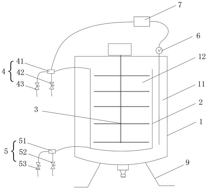
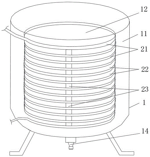
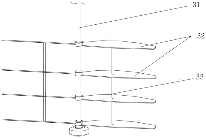
[0035] Such as Figure 1 to Figure 4 As shown, the present invention provides a crystal melting device for honey, including a tank 1 for loading honey. The tank 1 is provided with a matching heating and cooling assembly 2 and a stirring assembly 3, and the heating and cooling assembly 2 is provided by a pipe 21 is arranged in a spiral disk to form a hollow cylindrical body, and two adjacent layers of pipes 21 are spaced to form a pipe spacer layer 22; the head and tail of the pipe 21 extend out of the tank 1, and the head is provided with The first valve assembly 4 enables the pipeline 21 to communicate with the external high temperature medium source and the external cooling medium source at the same time, so that the high temperature medium enters the pipeline 21 when the crystal is melted / or the cooling medium enters the pipeline 21 after the crystal ...


PUM


Abstract

The invention discloses a crystal melting device for honey. A heating and cooling assembly and a stirring assembly are arranged in a tank body; the heating and cooling assembly is made of a helically coiled pipeline to form a hollow cylindrical body; a space is formed between every two adjacent up-down layers of the pipeline to form pipeline spacing layers; the head part and the tail part of the pipeline extend out of the tank body; a first valve assembly is arranged on the head part of the pipeline so that the pipeline simultaneously communicates with an external high-temperature medium source and an external cooling medium source to enable high-temperature mediums to enter the pipeline during crystal melting / or enable cooling mediums to enter the pipeline after crystal melting; a space is reserved between the heating and cooling assembly and the inner wall surface of the tank body to form an outer chamber; a hollow part of the heating and cooling assembly forms an inner chamber; and the stirring assembly enables the honey to flow back and forth between the inner chamber and the outer chamber through the pipeline spacing layers to achieve rapid uniform crystal melting or rapid uniform cooling. The crystal melting device disclosed by the invention has the advantages of being simple and compact in structure, high in degree of intelligence, easy in operation and maintenance, and high in crystal melting efficiency, and the honey quality can be effectively guaranteed.

Description

Technical field [0001] The invention mainly relates to the field of honey product processing and manufacturing equipment, in particular to a crystal melting device for honey. Background technique [0002] At present, in the production of honey, some honey raw materials, such as rape honey, linden honey, citrus honey, etc., will crystallize during storage, especially when the ambient temperature drops (below 15°C). Honey crystallization is a natural attribute of honey, but the crystallization of honey will bring great inconvenience to production and use. Crystallized honey needs to be melted at high temperature or even multiple times before it can be put into production. The existing honey melt crystal has the following technical problems: [0003] (1) In the prior art, part of the crystal melting method is to heat the inside of the crystal melting tank from outside, which will cause uneven heating inside the honey, low heat transfer efficiency, long crystal melting time, and seri...

Claims


Application Information

Patent Timeline
Patent Type & Authority Applications(China)
IPC IPC(8): A23L21/25
Inventor 邓长凤陈桥林
Owner 湖南省明园蜂业有限公司
Why Eureka
Try Eureka