
Radiotherapy system variable rectangular radiation field collimator

A radiation therapy and field collimator technology, which is applied in radiation therapy, treatment, X-ray/γ-ray/particle irradiation therapy, etc., can solve the problems of complex structure and high leakage rate of collimator, and achieve the goal of overcoming radiation leakage, Effect of reducing leakage rate and eliminating gaps

Pending Publication Date: 2017-05-24
SICHUAN UNIV
View PDF7 Cites 1 Cited by
  • Summary
  • Abstract
  • Description
  • Claims
  • Application Information

AI Technical Summary

Problems solved by technology

[0005] The purpose of the present invention is to overcome the defects of high leakage rate and complex structure of existing collimators, and propose a variable rectangular field collimator with simple structure, flexibility and high efficiency, and capable of realizing rectangular field intensity-modulated radiotherapy

Method used


Image

  • Radiotherapy system variable rectangular radiation field collimator
  • Radiotherapy system variable rectangular radiation field collimator
  • Radiotherapy system variable rectangular radiation field collimator

Examples


Embodiment Construction

[0030] The technical solutions of the present invention will be further described clearly and in detail below in conjunction with the accompanying drawings and embodiments. Apparently, the described embodiments are only part of the embodiments of the present invention, not all of them.

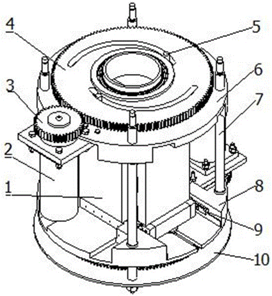
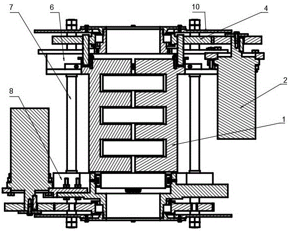
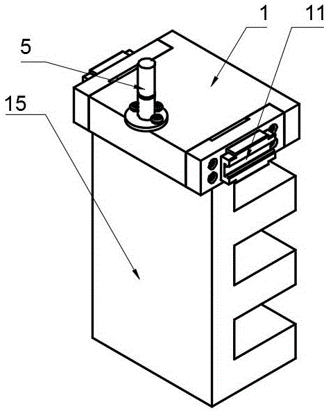
[0031] The variable rectangular field collimator in this example is as figure 1 , figure 2 and image 3 As shown, the collimator has a cylindrical shape as a whole and is composed of a block assembly 1 and a frame assembly 12. It is characterized in that a gear transmission mechanism 13 is symmetrically installed on the upper end surface and the lower end surface of the frame assembly 12, and the gear transmission mechanism 13 and the frame assembly 12 are connected by a rotary pair, and the gear transmission mechanism 13 can rotate relative to the frame assembly 12 under the drive of the motor; The block assembly 1 adopts a block 15 with a multi-layer structure, and each layer of multiple ...


PUM


Abstract

The invention discloses a radiotherapy system variable rectangular radiation field collimator which is composed of a stop block component and a rack component. The radiotherapy system variable rectangular radiation field collimator is characterized in that the upper end surface and the lower end surface of the rack component are symmetrically provided with a gear transmission mechanism. The gear transmission mechanisms and the rack component are connected through transmission pairs. The gear transmission mechanisms can rotate relative to the rack component under driving of a motor. The gear transmission mechanisms are connected with the pin shaft of the end surface of the stop block component through cam contour grooves. Stop blocks of a multilayer structure are adopted for the stop block component. The multiple stop blocks are installed in a staggered way in each layer so as to form a rectangular radiation field at the center. The radiotherapy system variable rectangular radiation field collimator is compact in structure and low in weight and can precisely realize ray collimation, and the stop blocks of the layered structure are adopted and installed in the staggered and clearance way so that the gap between the stop blocks can be greatly eliminated, the radiation leakage rate can be greatly reduced and the defects of radiation leakage and complex structure of the existing collimator can be overcome.

Description

technical field [0001] The invention relates to the field of medical equipment, in particular to a variable rectangular radiation field collimator for a radiotherapy system. Background technique [0002] Tumor has become the most common disease that threatens human life, and radiotherapy is one of the most important tumor treatment methods. The basic principle of radiotherapy is that high-energy rays are emitted from an accelerator, collimated by a collimator, and accurately projected to the tumor target area to kill cancer cells; the most commonly used collimators are conical collimators and multi-leaf gratings, but It is not the best choice for the pursuit of lightweight, flexible, high-quality and efficient robotic radiation therapy systems. [0003] Chinese patent ZL 201320000048.3 discloses a square variable field collimator. Although the square field can be adjusted continuously, it cannot be completely closed, so that the adjustable range of the field is relatively s...

Claims


Application Information

Patent Timeline
Patent Type & Authority Applications(China)
IPC IPC(8): A61N5/10
CPCA61N5/1001A61N5/1045A61N2005/1092
Inventor 杨亚茹李超姚进高文翔张世友吴杰蒋传魁
Owner SICHUAN UNIV
Learn More