Clean room with automatic entry dust collection device

An automatic dust removal and clean room technology, applied in the field of clean rooms, can solve the problems of less than dust removal effect, easily dirty floor mats, difficult to clean, etc., and achieve the effect of improving dust removal effect, reducing labor force, and convenient work

Pending Publication Date: 2017-05-24
重庆淳祥电子科技有限公司
View PDF24 Cites 3 Cited by
  • Summary
  • Abstract
  • Description
  • Claims
  • Application Information

AI Technical Summary

Problems solved by technology

[0003] 1) The outside air drawn by the fan is very dusty, so blowing the dusty air to the human body will not achieve the dust removal effect;
[0004] 2) The floor mat is very easy to get dirty and difficult to clean, and the effect of removing dust through the contact between the surface layer and the sole of the foot is not good;
[0005] 3) If multiple people enter the entrance passage at the same time, one person suddenly turns on the fan, which will cause others to be frightened

Method used


Image

  • Clean room with automatic entry dust collection device
  • Clean room with automatic entry dust collection device
  • Clean room with automatic entry dust collection device

Examples


Embodiment 1

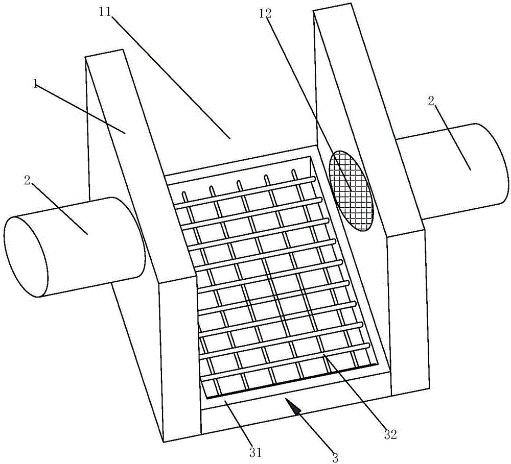
[0051] Such as figure 1 As shown, the present embodiment proposes a clean room with an automatic door dust removal device, including:

[0052] Two dust-removing walls 1, which are arranged at the entrance of the clean room, an entry passage 11 is formed between the two dust-removing walls 1, and air outlets are provided on the walls of the two dust-removing walls 1 near the entrance passage 11, and the air outlets are provided with fence 12;

[0053] Two blowers 2 are respectively installed on the two dust-removing walls 1, the input end of each blower fan 2 is connected to the outside air, and the output end of each blower fan 2 is respectively connected to the air outlet on the dust-removing wall 1 where they are respectively connected; and

[0054] The water tray 3 includes a tray body 31 for storing water. The tray body 31 is detachably installed on the ground of the entrance channel 11. The tray body 31 is provided with a support net 32 ​​to support the entry of the huma...

Embodiment 2

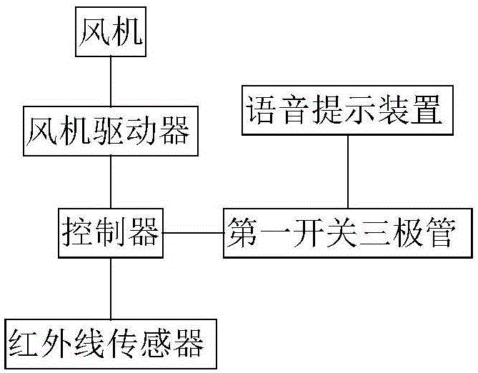
[0056] The difference between this embodiment and Embodiment 1 is that in order to prevent newcomers from entering the entrance passage 11 from being frightened by the sudden opening of the fan 2, a control circuit is designed in this embodiment.

[0057] The clean room with door automatic dust removal device in this embodiment also includes a control circuit, and the control circuit includes:

[0058] Fan 2 driver, its output end is connected with the motor of two fans 2;

[0059] A controller, the driving end of the fan 2 driver is connected to the first output end of the controller;

[0060] The first switching transistor, its base is connected to the second output terminal of the controller, and its emitter is grounded;

[0061] In the voice prompting device, the collector of the first switching transistor is connected to the negative pole of the voice prompting device, and the positive pole of the voice prompting device is connected to the power supply.

[0062] In order ...

Embodiment 3

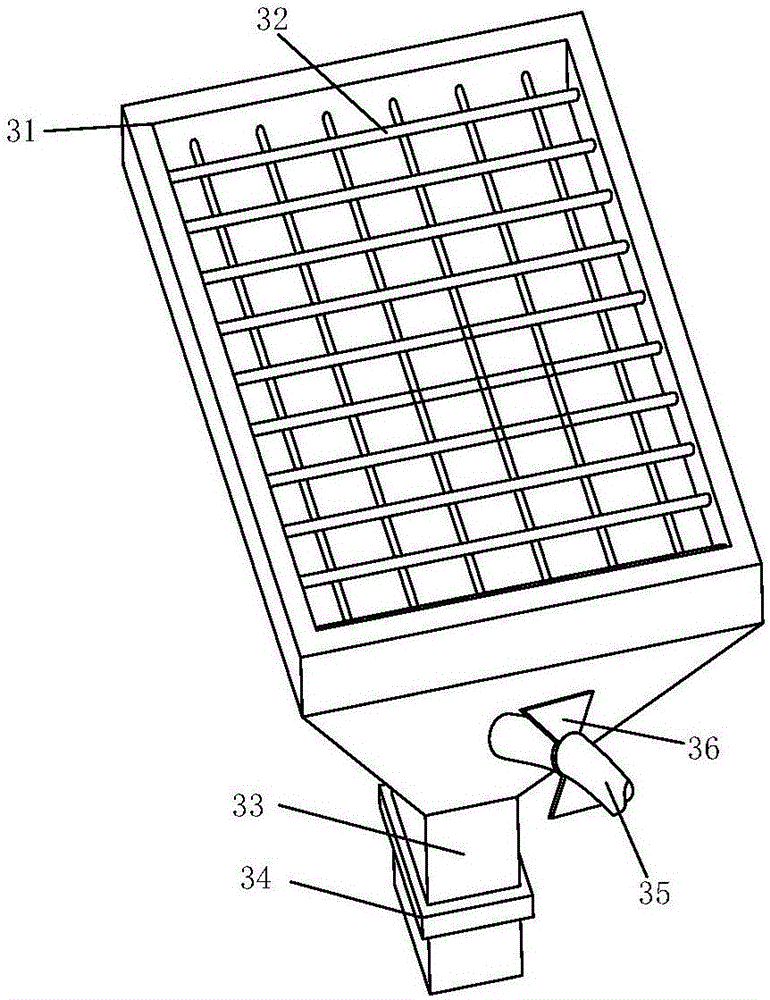
[0065] The difference between this embodiment and Embodiment 2 is that in order to realize the automatic water exchange of the water tray 3, the structure and control circuit of the water tray 3 are further designed in this embodiment.

[0066] Such as image 3 As shown, the bottom of the disc body 31 is a vertebral structure, the center of the bottom surface of the disc body 31 is connected with a first drain pipe 33, and the first drain pipe 33 is provided with a first electromagnetic valve 34 for opening and closing the first drain pipe 33, and the controller The third output end of the first solenoid valve is connected to the base of the second switching transistor, the negative pole of the first solenoid valve 34 is connected to the collector of the second switching transistor, the positive pole of the first solenoid valve 34 is connected to the power supply, and the disc body 31 is connected to the water inlet pipe 35 , the water inlet pipe 35 is provided with a third so...


PUM


Abstract

The invention provides a clean room with an automatic entry dust collection device. The clean room comprises two dust collection walls, two fans and a water containing tray, wherein the two dust collection walls are arranged at the entrance of the clean room, an entry channel is formed between the two dust collection walls, an exhaust opening is formed in the wall surface, close to the entry channel, of each of the two dust collection walls, and a fence is arranged on each exhaust opening; the two fans are mounted on the two dust collection walls respectively, the input end of each fan communicates with outside air, and the output end of each fan is connected and communicates with the exhaust opening in the corresponding dust collection wall; and the water containing tray comprises a tray body used for storing water, the tray body is detachably mounted on the ground of the entry channel, a supporting net is arranged in the tray body to support entering human bodies, and when the water containing tray is in use, water in the tray water spills over the supporting net. The clean room has the following beneficial effects: the sole dust collection effect is improved, and the water containing tray can be conveniently cleaned.

Description

technical field [0001] The invention relates to a clean room, in particular to a clean room with an automatic door dust removal device. Background technique [0002] The production of keyboard spacers requires the operation to be completed in a clean room. In the prior art, two dust-removing walls are arranged at the door of the clean room, and the two dust-removing walls communicate with the door to form an entry passage. Two fans are respectively arranged on the two dust-removing walls. Floor mats are laid on the floor. When the staff enters the entrance passage, press the switch, the branch where the two fans are located is powered on, the two fans work at the same time, blow the wind to the human body to remove the dust on the human body, step on the floor mat, and turn the soles of the feet Remove dust from the top. But the clean room has the following disadvantages: [0003] 1) The outside air drawn by the fan is very dusty, so blowing the dusty air to the human bo...

Claims


Application Information

Patent Timeline
Patent Type & Authority Applications(China)
IPC IPC(8): B08B3/04B08B5/02B08B13/00F04D29/70E04H5/02
CPCF04D29/703E04H5/02B08B3/04B08B5/02B08B13/00
Inventor 王灯亮
Owner 重庆淳祥电子科技有限公司
Why Eureka
Try Eureka