Drilling tool

A technology of drilling tools and cutting inserts, which is used in drilling tool accessories, drilling, and manufacturing tools, etc., can solve the problems of difficult balance of circumferential force, high frequency of tool change, cutting vibration, etc., to ensure the balance of force, The effect of reducing tool change frequency and cutting vibration

Active Publication Date: 2017-05-24
ZHUZHOU CEMENTED CARBIDE CUTTING TOOLS CO LTD
View PDF9 Cites 2 Cited by
  • Summary
  • Abstract
  • Description
  • Claims
  • Application Information

AI Technical Summary

Problems solved by technology

[0002] When the hole machining tool is cutting, the cutting end is mainly subjected to the cutting force. The spiral groove and the machined surface form a closed area. The chips can only be discharged from the cutting end through the spiral groove. It is difficult to remove the chips. In order to ensure the processing depth of the hole, the hole machining tool cutting The end generally has a large overhang. When the force on the cutting end is uneven, the cutting end will have a larger deflection than the clamped shank. At the same time, when the chips cannot be exhausted, the accumulated chips and spiral Severe scraping and extrusion are formed on the groove and the processed surface, and the tool body vibrates due to the unbalanced force in the circumferential direction, which not only reduces the quality of the processed surface, but also greatly reduces the life of the hole processing tool
[0003] In the prior art, in order to reduce the cost of tool use, the hole machining tool is usually designed with a split structure. The end cutting area is separated from the tool body to form a separate cutting unit. The clamping part forms a separate tool body. The cutting unit can be repeatedly loaded and unloaded on the On the cutter body, the cutting unit is composed of two blades, the inner blade and the outer blade, which respectively complete the processing of the small-diameter central column area and the large-diameter circumferential ring area of ​​the hole. Since the hole processing tool is required to have the ability to process blind holes and a set of inner blades, The combination of outer blades is applied to a variety of different diameter hole processing tools. Therefore, the cutting edge of the inner blade is required to be set across the central axis of the tool, while the outer blade is set adjacent to the processing surface. A complete cutting edge is formed by combining the inner blade and the outer blade. Since this type of hole processing tool adopts an asymmetrical cutting edge structure, the processing areas completed by the inner blade and the outer blade are different, so it is difficult to balance the circumferential force of the inner blade and the outer blade, and the torque generated during cutting is asymmetrical, which is easy to produce Deflection deformation and cutting vibration lead to large diameter error of machined hole and poor machined surface quality
[0004] In addition, when adjusting the assembly diameter of the inner blade and the outer blade, stress concentration is likely to occur in the overlapping area of ​​the inner blade and the outer blade, resulting in chipping of the blade, and it is easy to form thin and small chips that are pressed against the processed surface to reduce the quality of the processed surface, making it difficult to Ensure independent and stable cutting of inner and outer blades
At the same time, due to the large difference in cutting line speed between the inner blade and the outer blade, the outer blade has a greater material removal capacity than the inner blade, and the outer blade wears before the inner blade, that is, the life of the inner blade and the outer blade does not match, resulting in tool change frequency. High, increasing the difficulty of operation
In order to reduce the chipping of the peripheral edge of the outer blade caused by cutting vibration, the peripheral edge of the square outer blade and the processing surface generally have a certain inclined distance. When the cutting feed is large, the surface quality will be greatly reduced.

Method used


Image

  • Drilling tool
  • Drilling tool
  • Drilling tool

Examples


Embodiment Construction

[0027] The present invention will be further described in detail below in conjunction with the accompanying drawings and specific embodiments.

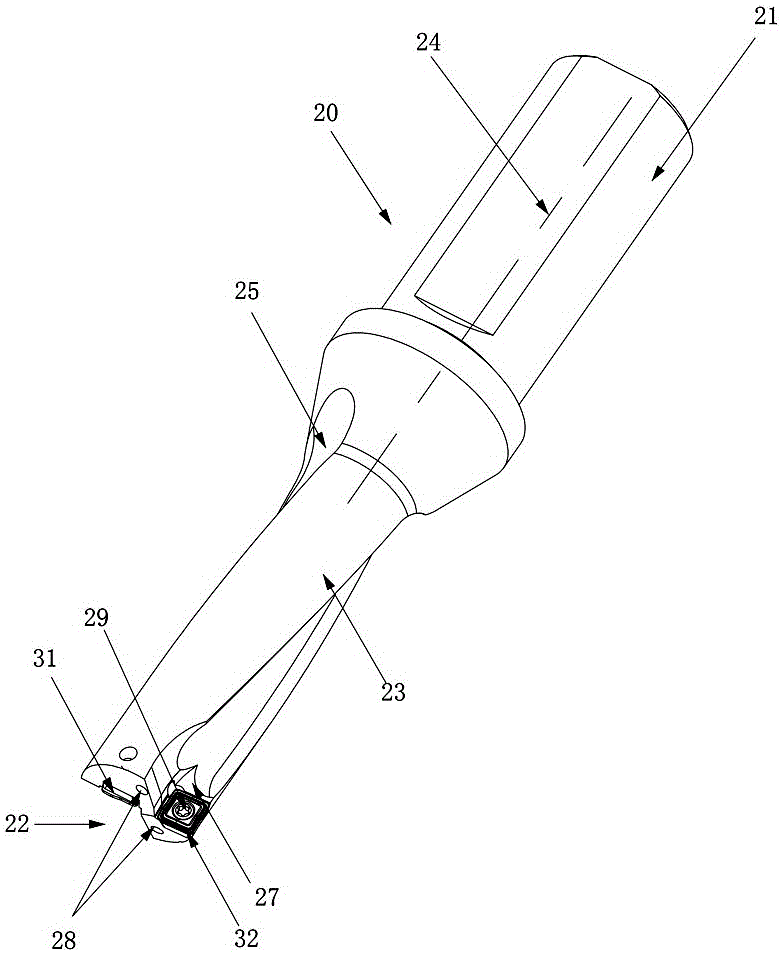
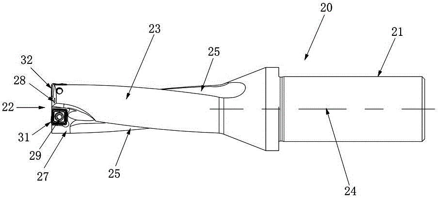
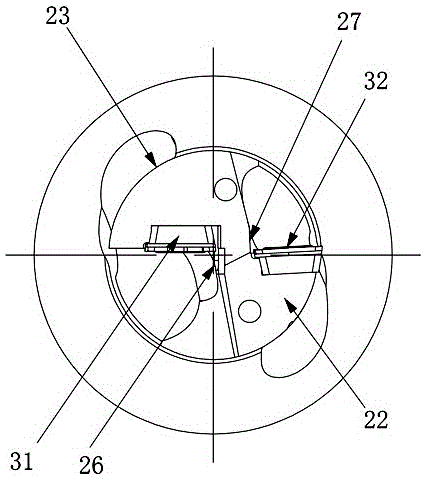
[0028] Figure 1 to Figure 7 A kind of embodiment of the drilling tool of the present invention is shown, the drilling tool of this embodiment comprises a cutter body 20, and the cutter body 20 comprises a shank 21, a cutting end 22 and a shank between the shank 21, the cutting end 22 Peripheral surface 23, shank portion 21, and peripheral surface 23 are all symmetrical about the center axis of rotation 24 of cutter body 20, and cutting end portion 22 is provided with a central groove 26 and a circumferential groove 27 communicating with spiral groove 25 on peripheral surface 23 , the central groove 26 is arranged adjacent to the central axis of rotation 24, and the circumferential groove 27 is arranged adjacent to the peripheral surface 23. Both the central groove 26 and the circumferential groove 27 are equipped with cutting blades,...


PUM


Abstract

The invention discloses a drilling tool. The drilling tool comprises a tool body; the tool body comprises a handle part, a cutting end part and a peripheral surface located between the handle part and the cutting end part; the handle part and the peripheral surface are symmetric about a rotation central axis of the tool body; a central groove and a circumferential groove which both communicate with a spiral groove in the circumferential surface are formed in the cutting end part, wherein the center groove is arranged adjacent to the rotation central axis, and the circumferential groove is arranged adjacent to the peripheral surface; cutting blades are arranged in the central groove and the circumferential groove, wherein the cutting blade arranged in the central groove is an inner blade, the cutting blade arranged in the circumferential grooves is an outer blade, and the inner blade and the outer blade are the same cutting blades; each cutting blade comprises a short cutting edge and a long cutting edge which are adjacent; the edge shape of each short cutting edge is different from the edge shape of the corresponding long cutting edge; the long cutting edge of the inner blade and the short cutting edge of the outer blade are combined to form a complete main cutting edge used for drilling a hole, the inner blade completes machining of a center area of the hole, and the outer blade completes machining of an outer ring area of the hole. The drilling tool has the advantages of being small in cutting vibration, high in machining precision, stable, reliable and the like.

Description

technical field [0001] The invention relates to the technical field of metal cutting, in particular to a drilling tool. Background technique [0002] When the hole machining tool is cutting, the cutting end is mainly subjected to the cutting force. The spiral groove and the machined surface form a closed area. The chips can only be discharged from the cutting end through the spiral groove. It is difficult to remove the chips. In order to ensure the processing depth of the hole, the hole machining tool cutting The end generally has a large overhang. When the force on the cutting end is uneven, the cutting end will have a larger deflection than the clamped shank. At the same time, when the chips cannot be exhausted, the accumulated chips and spiral The groove and the machined surface form severe scraping and extrusion, and the tool body vibrates due to the unbalanced force in the circumferential direction, which not only reduces the quality of the machined surface, but also gr...

Claims


Application Information

Patent Timeline
Patent Type & Authority Applications(China)
IPC IPC(8): B23B51/08
CPCB23B51/08
Inventor 王社权江爱胜刘敏李屏汤爱民项兴东王鹏
Owner ZHUZHOU CEMENTED CARBIDE CUTTING TOOLS CO LTD
Why Eureka
Try Eureka