
Internally-supported rotary tool head

A tool head and tool technology, applied in the direction of elements with teeth, gear teeth, belts/chains/gears, etc., can solve the problems of low grinding linear speed, loss of precision, excessive tool wear, etc., to achieve tool life and Improved machining efficiency, higher error homogenization, and improved machining line speed

Active Publication Date: 2017-05-24
SHANDONG UNIV OF TECH
View PDF6 Cites 0 Cited by
  • Summary
  • Abstract
  • Description
  • Claims
  • Application Information

AI Technical Summary

Problems solved by technology

However, at present, about 90% of domestic robots use imported precision reducers, and some imported precision reducers account for nearly 1 / 3 of the total cost of robots, which is one of the bottlenecks restricting the development of my country's robot industry.
A crucial reason for this phenomenon is that the internal tooth surface grinding machine tools required for precision reducers in my country have outstanding problems such as low grinding line speed, poor grinding accuracy, and low grinding efficiency, which have caused precision reducers Low precision, high noise, short life
The key problem is that the inner tooth surface is a closed curved surface, and the processing tool used must be smaller than the diameter of the addendum circle, which results in a small tool, which makes it very difficult to achieve the required processing speed, and also causes excessive wear of the tool. Induces excessive cost and loss of precision

Method used


Image

  • Internally-supported rotary tool head
  • Internally-supported rotary tool head
  • Internally-supported rotary tool head

Examples


Embodiment Construction

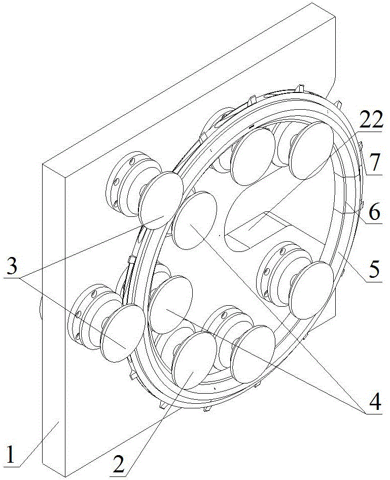
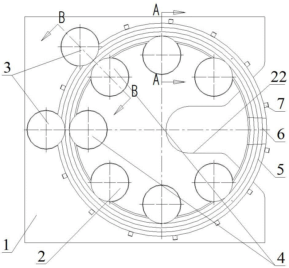
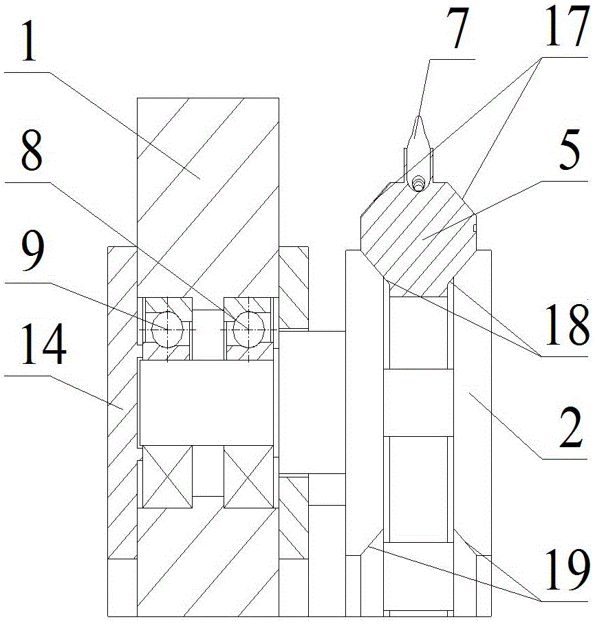
[0017] exist Figure 1-4 In the shown embodiment: including bracket 1, inner rotation support wheel shaft 2, outer friction drive wheel shaft 3, inner friction drive wheel shaft 4, tool wheel frame 5, plug 6, tool head 7, outer right bearing 8, outer left bearing 9. Inner right bearing 10, inner left bearing 11, left bearing 12, right bearing 13, upper end cover 14, middle end cover 15, lower end cover 16, outer raceway 17, inner raceway 18, inner roller raceway 19, outer The friction roller raceway 20, the inner friction roller raceway 21 and the open groove 22, wherein the inner rotating support axle 2 is positioned and supported on the bracket 1 through the outer right bearing 8, the outer left bearing 9 and the upper end cover 14, and the outer friction drive axle 3 passes through The inner right bearing 10, the inner left bearing 11 and the middle end cover 15 are positioned and supported on the bracket 1, and the inner friction drive wheel shaft 4 is positioned and suppo...


PUM


Abstract

The invention relates to an internally-supported rotary tool head which comprises a support, three or more internal rotary supporting wheel shafts, external friction driving wheel shafts, internal friction driving wheel shafts, a tool wheel frame, a plug, too head bodies and the like. The internally-supported rotary tool head is characterized in that the external friction driving wheel shafts and the internal friction driving wheel shafts are paired; the tool wheel frame and the plug and fixedly assembled; an outer roller path on the tool wheel frame is supported on inner roller paths on the internal rotary supporting wheel shafts; the outer roller path and an inner roller path on the tool wheel frame make contact with an outer friction roller path and an inner friction roller path on the external friction driving wheel shafts and the internal friction driving wheel shafts correspondingly; and the tool head bodies are fixedly mounted on the outermost side in the radial direction of the tool wheel frame. By adoption of the internally-supported rotary tool head, a rotary tool obtains a high machining line speed at a lower rotating speed, the limitation that an equal-size or smaller tool must be used for machining according to the small-size geometric features of parts is broken through, and the better machining quality and the longer tool life are achieved.

Description

technical field [0001] The invention relates to an internally supported rotary tool head, which belongs to the field of mechanical processing equipment. Background technique [0002] The R&D, manufacturing and application of industrial robots is an important symbol to measure the strength and level of a country's technological innovation and high-end manufacturing. In the next few years, the domestic demand for more than 2.4 million industrial robots accounts for about 70% of the world's total demand. Calculated in ten thousand yuan, the market size of industrial robots exceeds 720 billion yuan. However, at present, about 90% of domestic robots use imported precision reducers, and some imported precision reducers account for nearly 1 / 3 of the total cost of robots, which is one of the bottlenecks restricting the development of my country's robot industry. A crucial reason for this phenomenon is that the internal tooth surface grinding machine tools required for precision red...

Claims


Application Information

Patent Timeline
Patent Type & Authority Applications(China)
IPC IPC(8): B23F1/02
CPCB23F1/02
Inventor 程祥刘原勇郑光明杨先海徐汝锋刘肖肖
Owner SHANDONG UNIV OF TECH
Learn More