Supercharge Your Innovation With Domain-Expert AI Agents!

Reflow soldering furnace and control system thereof

A reflow soldering furnace and control device technology, applied in welding equipment, manufacturing tools, metal processing equipment, etc., can solve the problems of reducing production efficiency, taking a long time, and increasing costs, so as to save energy, save inert gas, and ensure The effect of production efficiency

Inactive Publication Date: 2017-05-24
NANTONG FUJITSU MICROELECTRONICS
View PDF5 Cites 9 Cited by
  • Summary
  • Abstract
  • Description
  • Claims
  • Application Information

AI Technical Summary

Problems solved by technology

This kind of nitrogen supply method will continue to fill nitrogen when the reflow oven is waiting for material, which will cause an increase in cost and a waste of resources.
Therefore, when the reflow oven is waiting for materials for a long time, in order to save nitrogen, the reflow oven will be turned off, and the reflow oven will be turned on again when the material is put into production, but it will take a long time to restart the reflow oven, which will reduce production efficiency.

Method used


Image

  • Reflow soldering furnace and control system thereof
  • Reflow soldering furnace and control system thereof
  • Reflow soldering furnace and control system thereof

Examples


Embodiment Construction

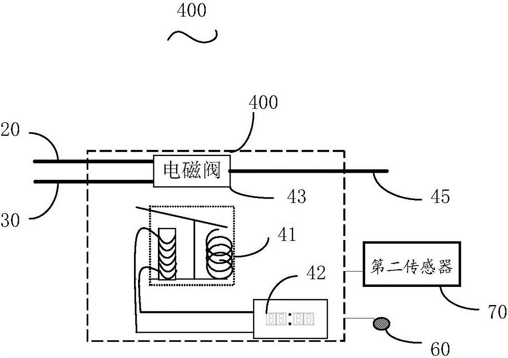
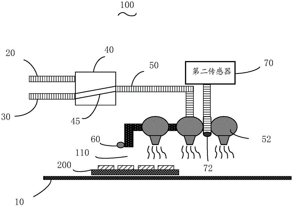
[0021] See figure 1 , figure 1 It is a schematic diagram of the structure of the first embodiment of the reflow soldering furnace 100 of the present invention, including a conveying device 10, a first input pipe 20, a second input pipe 30, a pipe control device 40, an air outlet pipe 50, a first sensor 60 and a second Sensor 70.

[0022] In this embodiment, the conveying device 10 is a guide rail capable of horizontal and bidirectional transmission, and the conveying device 10 penetrates the reflow oven 100. The reflow soldering furnace 100 is provided with a feed opening 110, and the product 200 enters the cavity of the reflow soldering furnace 100 along the conveying device 10 through the feed opening 110. The first sensor 60 is disposed on the outside of the furnace wall 120 of the reflow soldering furnace 100 adjacent to the inlet 110. The first sensor 60 is a feed sensor and is used to detect whether a product enters the reflow oven 100. The second sensor 70 is an oxygen a...


PUM


Abstract

The invention discloses a reflow soldering furnace which comprises a conveying mechanism, a first input pipe, a first sensor and a pipe control device. A product is conveyed into the reflow soldering furnace through the conveying mechanism, inert gas is input into the reflow soldering furnace through the first input pipe, the first sensor detects whether the product exists in the reflow soldering furnace or not, and the pipe control device is coupled with the first sensor and controls the first input pipe to stop or reduce inert gas input within at least part of time in the period when no product is detected in the reflow soldering furnace. By means of the above manner, inert gas input can be stopped or reduced when no product exists in the reflow soldering furnace; and under the condition that the reflow soldering furnace is not closed, the production cost is reduced, and the production efficiency is improved. The invention further discloses a control system of the reflow soldering furnace.

Description

Technical field [0001] The invention relates to the field of soldering, in particular to a reflow soldering furnace and its control system. Background technique [0002] At present, reflow soldering is widely used in the field of electronic component manufacturing. For example, in the chip packaging process, after the chip packaging is completed, it needs to go through a reflow oven to complete the soldering of bumps and substrate pads or circuits. In the reflow process, in addition to the need to control the temperature curve In addition, it is also necessary to control the oxygen content in the furnace to ensure welding quality. The control of the oxygen content is achieved by filling the furnace cavity with inert gas, such as nitrogen. [0003] Under normal circumstances, nitrogen is continuously filled into the furnace cavity through the pipeline after the reflow furnace is started, so as to ensure that the oxygen content in the reflow furnace is below a certain set value. Thi...

Claims


Application Information

Patent Timeline
Patent Type & Authority Applications(China)
IPC IPC(8): B23K3/00B23K3/08
CPCB23K3/00B23K3/08
Inventor 严小龙卢海伦周锋施陈
Owner NANTONG FUJITSU MICROELECTRONICS
Features
  • R&D
  • Intellectual Property
  • Life Sciences
  • Materials
  • Tech Scout
  • Unparalleled Data Quality
  • Higher Quality Content
  • 60% Fewer Hallucinations
Learn More