
Novel laser engraving unit equipment

A new type of laser engraving technology, used in laser welding equipment, welding equipment, metal processing equipment, etc., can solve the problems of difficult cleaning, engraving machine failure, easy aging, etc., to eliminate surrounding static electricity, save cleaning time, and avoid static electricity interference Effect

Inactive Publication Date: 2017-05-24
TIANJIN ZHONGDING ALUMINUM IND CO LTD
View PDF0 Cites 2 Cited by
  • Summary
  • Abstract
  • Description
  • Claims
  • Application Information

AI Technical Summary

Problems solved by technology

[0002] Improved laser engraving performance Sculpture The efficiency makes the surface of the engraved place smooth and round. When processing metal surfaces, laser engraving machines are often used. In order to meet the factory's assembly line processing, traditional engraving machines are mostly open, but there is too much dust in the factory, and the machine takes a long time. Exposure to the air is very easy to age, leading to failure of the engraving machine; the laser engraving machine will generate a lot of metal debris during the engraving process, the traditional engraving machine does not have the collection function, it is very difficult to clean up after use, and it takes a lot of time to clean it manually; the traditional During the engraving process of the laser engraving machine, if there is static electricity around, it is very easy to affect the engraving depth, resulting in different engraving depths

Method used


Image

  • Novel laser engraving unit equipment

Examples


Embodiment 1

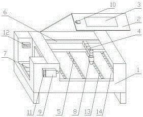
[0009] A new type of laser engraving unit equipment, including: body 1, machine cover 2, observation port 3, telescopic frame 4, slag collection tank 5, guide rail 6, console 7, laser transmitter 8, photoelectric receiver 9, photoelectric transmitter Device 10, buzzer 11, automatic static eliminator 12, exhaust fan 13, engraving table 14, machine cover 2 is installed on the top of the body 1, an observation port 3 is opened on the machine cover 2, and a photoelectric transmitter is installed on one side of the observation port 3 10. A console 7 is installed on one side of the fuselage 1, a fully automatic static eliminator 12 is installed on one side of the console 7, a photoelectric receiver 9 is installed on one side of the console 7, a buzzer 11 is installed on one side of the photoelectric receiver 9, the fuselage 1 The engraving table 14 is installed at the bottom, the slag collection tank 5 is set on the engraving 14 table, the exhaust fan 13 is installed in the slag coll...

Embodiment 2

[0011] Place the metal to be engraved on the engraving table 14, close the machine cover 2, start engraving after setting the engraving pattern through the console 7, and the laser emitter 8 emits laser light to engrave the metal surface on the engraving table 14. If the machine cover 2 is not If it can be completely closed, the photoelectric receiver 9 cannot receive the photoelectric signal emitted by the photoelectric transmitter 10, triggering the buzzer 11 to sound an alarm. During the engraving process, the exhaust fan 13 sucks the generated debris and dust into the slag collection tank 5 , Fully automatic static eliminator 12 can automatically remove static electricity around to avoid static interference.


PUM


Abstract

The invention relates to novel laser engraving unit equipment which comprises a machine body, a machine cover and the like. The novel laser engraving unit equipment is characterized by further comprising a photoelectric receiver, a slag collecting groove, a photoelectric transmitter, a buzzer, a full-automatic electrostatic eliminator and an exhaust fan; and the machine cover is installed above the machine body and is provided with an observation opening, the photoelectric transmitter is installed on one side of the observation opening, a control table is installed on one side of the machine body, the full-automatic electrostatic eliminator is installed on one side of the control table, and the photoelectric receiver is installed on one side of the control table. By means of the exhaust fan, chippings and dust can be sucked into the slag collecting groove, equipment aging caused by too much dust is avoided, meanwhile, waste slag is more easily removed, and a large amount of cleaning time is saved; in the engraving process, the photoelectric transmitter will transmit photoelectric signals continuously, if the machine cover is not closed, the photoelectric receiver cannot receive the photoelectric signals, the buzzer is triggered to make a sound and give out an alarm, and a worker is prompted that the machine cover is not closed; and the full-automatic electrostatic eliminator can automatically eliminate surrounding static, and static interference is avoided.

Description

technical field [0001] The invention relates to a metal surface processing equipment, in particular to a novel laser engraving unit equipment. Background technique [0002] Improved laser engraving performance Sculpture The efficiency makes the surface of the engraved place smooth and round. When processing metal surfaces, laser engraving machines are often used. In order to meet the factory's assembly line processing, traditional engraving machines are mostly open, but there is too much dust in the factory, and the machine takes a long time. Exposure to the air is very easy to age, leading to failure of the engraving machine; the laser engraving machine will generate a lot of metal debris during the engraving process, the traditional engraving machine does not have the collection function, it is very difficult to clean up after use, and it takes a lot of time to clean it manually; the traditional During the engraving process of the laser engraving machine, if there is stat...

Claims


Application Information

Patent Timeline
Patent Type & Authority Applications(China)
IPC IPC(8): B23K26/362B23K26/16B23K26/70
CPCB23K26/16
Inventor 张小磊
Owner TIANJIN ZHONGDING ALUMINUM IND CO LTD
Learn More