
Cam driven mechanical hand

A technology of manipulator and cam transmission, which is applied in manipulators, program-controlled manipulators, manufacturing tools, etc. It can solve the problems of low air pressure driving precision, slow movement speed, and large impact vibration, etc., and achieves simple driving methods, low manufacturing costs, and guaranteed The effect of stability

Pending Publication Date: 2017-05-24
HUNAN SUPER INFORMATION
View PDF7 Cites 5 Cited by
  • Summary
  • Abstract
  • Description
  • Claims
  • Application Information

AI Technical Summary

Problems solved by technology

In order to realize this work, there are the following two structures in the prior art to complete this action: 1) The grasping and placing manipulator driven by air pressure, this kind of structure is simple, flexible and convenient to install, low in purchase cost, and can only realize simple grasping And moving action, the grasping force driven by air pressure is small, and it can only move in a straight line when moving. Slow; 2) The motor drives the grabbing and placing manipulator. This structure has a large grabbing force, is easy to install, has high flexibility, and can be docked at multiple points. If the assembly system needs to be changed or redesigned, simply reprogram it. However, motor-driven manipulators need to be equipped with complex electrical control systems. If such manipulators are used to complete relatively simple repetitive tasks, the cost will be high. The cooperation of multiple motors can achieve multi-axis transmission, and the movement speed is relatively fast. However, when The faster the movement speed, the greater the error, which affects the movement error. It is difficult to accurately control the acceleration and speed of the manipulator movement, especially when it stops, the action is blunt and the impact vibration is large. Moreover, this structure can only move along a straight line. Need When positioning and moving, only horizontal and vertical linear movements can be staggered. In addition, this structure has a large volume and requires a combination of multiple sets of mechanical arms. In addition to the driving structure, the overall volume is large

Method used


Image

  • Cam driven mechanical hand
  • Cam driven mechanical hand
  • Cam driven mechanical hand

Examples


Embodiment Construction

[0023] The present invention will be further described in detail below in conjunction with the accompanying drawings and specific embodiments.

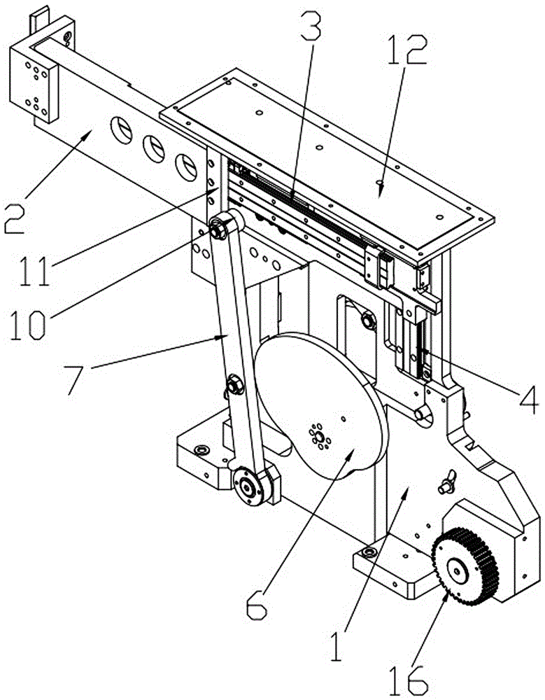
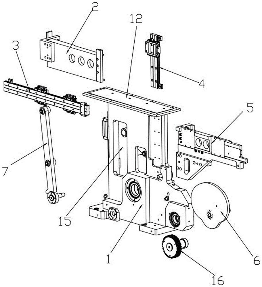
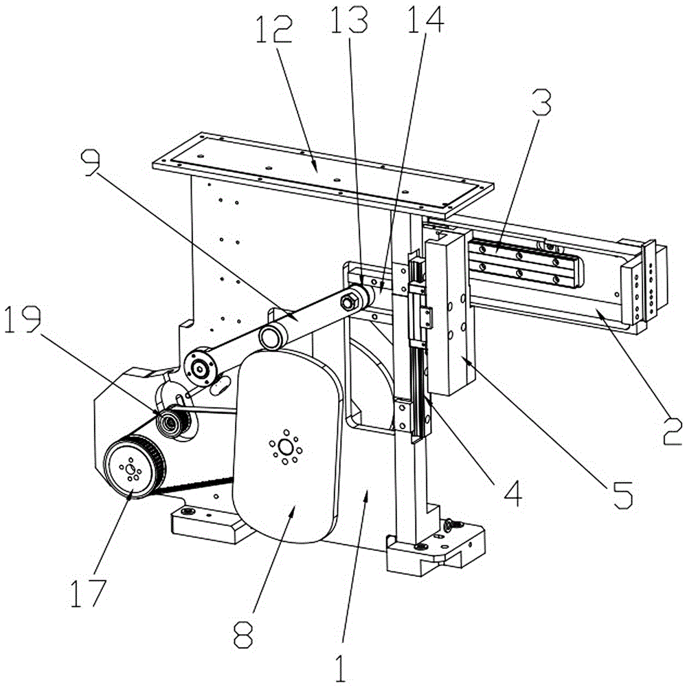
[0024] In this embodiment, refer to Figure 1 ~ Figure 4 , the cam-driven manipulator of its specific implementation includes a main board 1, a guide rail assembly, a horizontal bracket 2 and a synchronous transmission assembly. The main board 1 is a vertical structure. Guide rail 3 and vertical guide rail 4, vertical guide rail 4 is provided with a group altogether, is vertically installed on the front and rear ends of main board 1 respectively, and is provided with main support 5 on the slide block of vertical guide rail 4, makes main support 5 can Sliding up and down along the vertical guide rail 4, the horizontal bracket 2 is fixedly installed on the front end of the horizontal guide rail 3, the slider of the horizontal guide rail 3 is installed on one side of the main bracket 5, and the inner side of the horizontal bracket 2 is p...


PUM


Abstract

The invention relates to a cam driven mechanical hand and belongs to the field of mechanical transmission equipment. The cam driven mechanical hand comprises a main plate, a guide rail assembly, a horizontal support and a synchronous drive assembly. A first cam drive assembly is arranged on the left side of the main plate. A second cam drive assembly is arranged on the right side of the main plate. The first cam drive assembly is composed of a horizontal cam and a first rocking rod. The second cam drive assembly is composed of a vertical cam and a second rocking rod. The horizontal cam and the vertical cam are jointly driven by the synchronous drive assembly to achieve synchronous rotation. The whole mechanical hand can be manufactured to be of a flat small structure and is extremely small in occupied space. The first cam drive assembly and the second cam drive assembly are combined so as to drive the horizontal support to achieve an arc movement locus, the mechanical hand can precisely move to any point through the arc locus, it is ensured that overall operation of the mechanical hand is stable, no vibration is produced so as to ensure assembly stability, and the cam drive structure is high in precision and particularly applicable to automatic machining or assembly with high requirements for precision.

Description

technical field [0001] The invention relates to the field of mechanical transmission equipment, in particular to cam transmission technology, and in particular to a cam-driven manipulator. Background technique [0002] In automatic assembly operations, the manipulator is often required to perform the simplest action: grab the workpiece at a certain position, and then put it down at another position to realize feeding, processing, assembly and other actions. In order to realize this work, there are the following two structures in the prior art to complete this action: 1) The grasping and placing manipulator driven by air pressure, this kind of structure is simple, flexible and convenient to install, low in purchase cost, and can only realize simple grasping And moving action, the grasping force driven by air pressure is small, and it can only move in a straight line when moving. Slow; 2) The motor drives the grabbing and placing manipulator. This structure has a large grabbi...

Claims


Application Information

Patent Timeline
Patent Type & Authority Applications(China)
IPC IPC(8): B25J9/00B25J9/10
CPCB25J9/00B25J9/0009B25J9/10
Inventor 胡炎良
Owner HUNAN SUPER INFORMATION
Learn More