
Automobile floating-charge air conditioner

A technology for air conditioners and floating charging, which is applied to vehicle components, air handling equipment, heating/cooling equipment, etc., and can solve problems such as increased manufacturing and use costs, rising cost of system components, and inconvenient applications.

Inactive Publication Date: 2017-05-24
孙善骏
View PDF0 Cites 0 Cited by
  • Summary
  • Abstract
  • Description
  • Claims
  • Application Information

AI Technical Summary

Problems solved by technology

[0002] The inventor invented this type of car floating air conditioner with rich structure before, and the existing vehicle air conditioner only has a separate power-driven air conditioner mode in the car, which wastes a lot of energy and materials, and also increases other systems. The cost of manufacturing and use is reduced; the existing vehicle air conditioners and air ventilation adjustments completely use the power system in the vehicle, resulting in low efficiency of the power system and an increase in the cost of system components; the existing vehicle air conditioners and air ventilation adjustments are also contradictory and inconvenient to use. In particular, electric vehicles have higher requirements for energy utilization efficiency, which often depends on whether they have a more efficient air-conditioning system. If the battery is used for cooling and heating alone, the mileage of electric vehicles will be reduced by about 60%. Refrigeration and heating are difficult to apply. In order to improve this unfavorable situation, it is necessary to invent a suitable and advanced device that can cool and heat when walking, float and charge cold and heat energy and electric energy, absorb and utilize external energy, and resolve resistance energy. device, that is, the automobile floating air conditioner of the improved invention

Method used


Image

  • Automobile floating-charge air conditioner
  • Automobile floating-charge air conditioner
  • Automobile floating-charge air conditioner

Examples


specific Embodiment approach

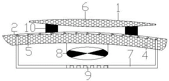
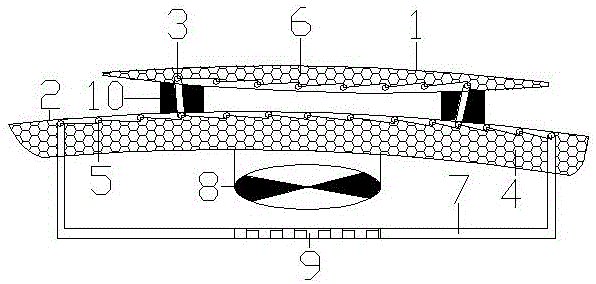
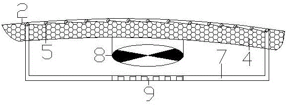
[0009] Specific implementation method: the lower wing compartment body conduit (5) and / or the upper wing duct (3) are connected to the heat pipe (7) and the heat pipe cooling fin (9) to form a heat pipe circulation system; the lower wing is arranged under the surface of the compartment body The carriage body conduit (5) and the upper attached wing conduit (3) are arranged on the lower inner surface of the upper attached wing (1). When the vehicle is running, the airflow generated between the upper wing (1) and the lower wing body (2) by the vehicle running and the wind flows between them, because the upper wing (1) and the lower wing body (2) ) between the airflow speed will greatly reduce the throat temperature between them to produce cooling capacity, in order to prevent the loss of the generated cooling capacity, on the inner side of the lower wall of the upper wing (1) installed with the upper wing duct (3) and the inner side of the upper wall of the lower wing compartment...


PUM


Abstract

The invention provides an automobile floating-charge air conditioner. The automobile floating-charge air conditioner mainly comprises an upper flap, a lower flap carriage body, an upper flap duct, a carriage heat insulation layer, a lower flap carriage body duct, an upper flap heat insulator, a heat tube, a fan, a heat tube cooling fin and a supporting sleeve; a certain angle is formed between the lower flap carriage body and the upper flap; the air flows through between the lower flap carriage body and the upper flap; and as the speed of the air between the lower flap carriage body and the upper flap is high, the throat temperature between the lower flap carriage body and the upper flap is greatly reduced to manufacture cooling capacity and the cooling capacity is conveyed into a heat tube system to be utilized. Through adoption of the mode, air kinetic energy and solar energy can be decomposed for refrigeration and heating in the running of a motor vehicle and the obtained cold and heat are recycled by a vehicle air conditioner and an air conditioning system; therefore, purposes of refrigerating and heating, charging cold energy, heat energy and electric energy in a floating manner, absorbing and utilizing outside energy and decomposing drag energy are realized.

Description

technical field [0001] The invention relates to the field of motor vehicles, and is a floating air conditioner for automobiles that fully utilizes aerodynamic force, wind power and solar energy. It can use air kinetic energy and solar energy to cool and heat the vehicle air conditioner and air during the operation of the motor vehicle. The system device scheme for regulating and reusing is applicable to various motor vehicles, and is also applicable to the application on electric vehicles. Background technique [0002] The inventor invented this type of car float air conditioner with rich structure before, and the existing vehicle air conditioner only has a separate power-driven air conditioner mode in the car, which wastes a lot of energy and materials, and also increases other systems. The cost of manufacturing and use is reduced; the existing vehicle air conditioners and air ventilation adjustments completely use the power system in the vehicle, resulting in low efficienc...

Claims


Application Information

Patent Timeline
IPC IPC(8): B60H1/32B60H1/22
CPCB60H1/3202B60H1/22B60H1/3235B60H2001/2268
Inventor 孙善骏
Owner 孙善骏
Learn More