Road cleaning equipment

A kind of equipment and cleaning technology, applied in the direction of road cleaning, construction, cleaning methods, etc., can solve the problems of reducing garbage storage space, cleaning difficulties, air pollution, etc., to avoid secondary dust pollution, good dust removal effect, and simple structure Effect

Inactive Publication Date: 2017-05-24
朱章 +1
View PDF8 Cites 0 Cited by
  • Summary
  • Abstract
  • Description
  • Claims
  • Application Information

AI Technical Summary

Problems solved by technology

[0002] The current road cleaning is mainly based on cleaning. At present, the cleaning machinery used in the city is also equipped with a water spray system at the front or in the middle of the vehicle. The floating dust on the road surface will be condensed through the washing of water, and will not cause secondary dust during the cleaning process. Road surface A large amount of water condenses dust, and the dust remains after the water evaporates, causing waste of water resources. Basically, the cleaning method is rubbish, and the dust cannot be cleaned. Some small dust is also released into the atmosphere during cleaning, bringing To prevent secondary pollution, in order to prevent dust during the cleaning process, water was continuously sprayed on the ground and brushes, but the result was that the dust mixed into mud and stuck to the ground, and when the water evaporated, the dust would be transported by cars again. Air pollution is caused by the air flow or wind blowing. This solution has many disadvantages. First, the muddy water on the road surface has a large proportion, and the dust suction port cannot suck all the muddy water. After drying, it is still dust, which greatly reduces the vacuuming effect of the sweeper
The second is that the muddy water adheres to the i

Method used


Image

  • Road cleaning equipment

Examples


Embodiment Construction

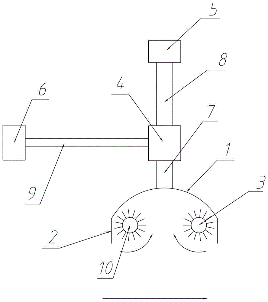
[0023] The present invention is a kind of road cleaning equipment, which comprises a motorized traveling device and an engine driving the motorized traveling device. The motorized traveling device can be various motor vehicles or other motorized devices. The base of the motorized traveling device is connected with a position adjustable Adjustable airflow fairing 1, the airflow fairing 1 can move up, down, left, right, forward and backward within a certain range through the position adjustment device for position adjustment.

[0024] The position adjustment device is used to adjust the position of the airflow fairing 1, and the position adjustment device is driven by the driving device. The airflow fairing 1 can be arranged in front of the front wheel of the vehicle or other motor equipment or behind the rear wheel, and can also be arranged in the Between the front and rear wheels, the airflow fairing 1 is connected with air exhaust equipment and dust collection and exhaust syst...


PUM


Abstract

The invention relates to the field of road sweeping and dust removal, in particular to road cleaning equipment which comprises maneuvering traveling equipment and an engine driving the maneuvering traveling equipment. An airflow fairing is arranged on a base of the maneuvering traveling equipment and connected with air suction equipment and a dust removing and collecting exhausting system through a main airflow pipeline, the airflow fairing is an inverted container, and an opening is formed in one side, facing the bottom surface, of the airflow fairing; and two cleaning wheels are further arranged in the airflow fairing, and the two cleaning wheels, namely the auxiliary cleaning wheel and the main cleaning wheel, are sequentially arranged front and back in the traveling direction of the maneuvering traveling equipment. The road cleaning equipment is simple in structure, garbage and dust are collected through the main cleaning wheel, negative pressure is formed in the airflow fairing, the garbage and the dust are sucked into a separating device through the main airflow pipeline, and the garbage and the dust are separately processed, so that the purpose of road dust removal is achieved, and secondary dust raising pollution is avoided.

Description

technical field [0001] The invention relates to the field of road garbage cleaning and dust removal, in particular to road cleaning equipment. Background technique [0002] The current road cleaning is mainly based on cleaning. At present, the cleaning machinery used in the city is also equipped with a water spray system at the front or in the middle of the vehicle. The floating dust on the road surface will be condensed through the washing of water, and will not cause secondary dust during the cleaning process. Road surface A large amount of water condenses dust, and the dust remains after the water evaporates, causing waste of water resources. Basically, the cleaning method is rubbish, and the dust cannot be cleaned. Some small dust is also released into the atmosphere during cleaning, bringing To prevent secondary pollution, in order to prevent dust during the cleaning process, water was continuously sprayed on the ground and brushes, but the result was that the dust mixe...

Claims


Application Information

Patent Timeline
IPC IPC(8): E01H1/08
CPCE01H1/0845
Inventor 朱章朱天命
Owner 朱章
Why Eureka
Try Eureka