
Hydro-pneumatic suspension cylinder with controllable stroke

A technology of oil-pneumatic suspension and travel, applied in the direction of suspension, elastic suspension, gas-hydraulic shock absorber, etc., can solve the problems of not considering external input ports and internal control links, limitations, lack of structural foundation and conditions, etc.

Pending Publication Date: 2017-05-24
张宏如
View PDF0 Cites 2 Cited by
  • Summary
  • Abstract
  • Description
  • Claims
  • Application Information

AI Technical Summary

Problems solved by technology

The existing various oil-pneumatic suspension cylinder structures lack the structural basis and conditions for complete realization
[0024] 5. The existing oil-pneumatic suspension cylinders of various structures focus on the combination of the internal stiffness and damping characteristics of the suspension cylinder itself, as well as the integrity and reliability of independent operation, and do not consider the setting of the external input port and the external active control. Internal control link
However, it is limited to the suspension components, the working capacity, control capacity, system accuracy and cost composition of the electronic control system, and is greatly restricted in the application of large vehicles and popular products.

Method used


Image

  • Hydro-pneumatic suspension cylinder with controllable stroke
  • Hydro-pneumatic suspension cylinder with controllable stroke
  • Hydro-pneumatic suspension cylinder with controllable stroke

Examples


Embodiment Construction

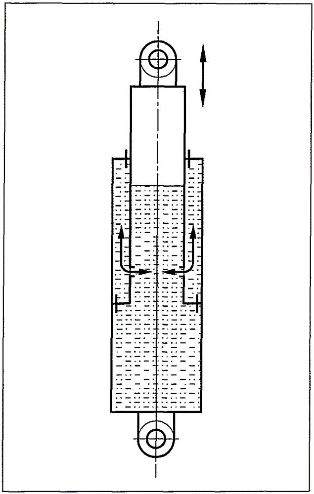
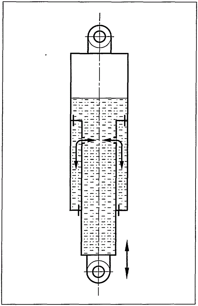
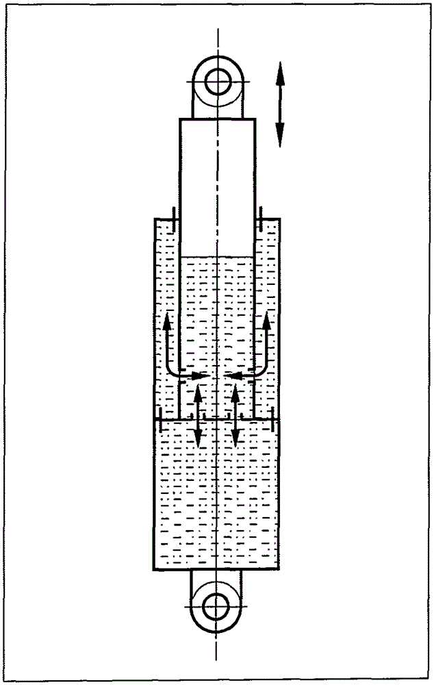
[0095] In this patent, the stroke-controllable oil-pneumatic suspension cylinder includes a piston rod 10, a piston 11, an internal control valve group 12, a cylinder barrel 13, a sealing seat ring 14, an accumulator 15, a control valve 16, a gas-liquid booster pump 17, and a flow control Cylinder 18, reversing valve 19, pipeline 25. The cylinder 13, the piston rod 10 and the piston 11 enclose a suspension cylinder inner cavity 20 (rodless cavity) inside the suspension cylinder. Described cylinder barrel 13, seal seat ring 14 and piston rod 10, piston 11 encircle auxiliary oil chamber 21 (rod chamber) between the side walls of the waist of the suspension cylinder. The auxiliary oil chamber 21 is filled with hydraulic oil and is completely isolated from the inner chamber 20 of the suspension cylinder. The suspension cylinder inner cavity 20 is divided into a cylinder inner cavity 22 and a piston rod inner cavity 23 by an internal control valve group 12 at the bottom of the pis...


PUM


Abstract

The invention discloses a hydro-pneumatic suspension cylinder with a controllable stroke. The hydro-pneumatic suspension cylinder comprises a piston rod, a piston, an internally piloted valve group, a cylinder barrel, a sealing seat ring, an energy storage device, a control valve, a pipeline, a gas-liquid booster pump and a flow rate control cylinder. The suspension cylinder internally comprises an auxiliary oil cavity and an inner cavity of the suspension cylinder, wherein the auxiliary oil cavity is completely isolated from the inner cavity of the suspension cylinder. The inner cavity of the suspension cylinder comprises an inner cavity of the cylinder barrel and an inner cavity of the piston rod, and the middles are communicated through the internally piloted valve group to form a complete inner cavity system of the suspension cylinder. The auxiliary oil cavity is externally connected with the control valve and the energy storage device through the pipeline to form an independent external control loop. The external control connectors of the gas-liquid booster pump and the flow rate control cylinder are connected with the inner cavity system of the suspension cylinder and the external control loop respectively to form two independent channels for equal-pressure / synchronous control. Stroke control on the suspension cylinder is realized through the operation of inner reversing valves of the gas-liquid booster pump and the flow rate control cylinder. The inner cavity system of the suspension cylinder and the external control loop form a double-air-chamber negative pressure opposite structure through the inner cavity of the cylinder barrel and the auxiliary oil cavity. The internally piloted valve group carries out automatic variable-damping control on the inner cavity system of the suspension cylinder according to a system pressure.

Description

technical field [0001] This patent relates to an oil and gas suspension cylinder, and specifically discloses a controllable stroke oil and gas suspension cylinder, and discloses its new structural characteristics and use functions. Background technique [0002] The oil and gas suspension cylinder integrates the structural principles and functions of air springs and hydraulic dampers, and has better mechanical properties and application scope. The inside of the oil and gas suspension cylinder is filled with nitrogen gas and hydraulic oil. Nitrogen, as an elastic medium and energy storage medium, has variable stiffness characteristics and has a larger energy storage ratio than metal elastic materials. Hydraulic oil is used as a damping medium to generate damping force through the damping structure inside the suspension cylinder. [0003] Because the nitrogen gas is encapsulated within the cylinder structure, the hydro-pneumatic suspension cylinder has a greater working press...

Claims


Application Information

Patent Timeline
IPC IPC(8): F16F9/06F16F9/512F16F9/58F16F9/34B60G17/048B60G17/056
Inventor 张宏如
Owner 张宏如
Learn More