Servo-pump-controlled hydraulic rotary driving system and control method

A technology of slewing drive and servo drive, which is applied in transmission control, transmission, fluid transmission, etc. It can solve the problems of difficult hydraulic motor servo control, increase system loss, difficult maintenance, etc., and achieve wide-range speed ratio adjustment, The effect of high reliability of the oil circuit and simple system structure

Active Publication Date: 2017-05-24
桂林星辰科技股份有限公司 +1
View PDF8 Cites 15 Cited by
  • Summary
  • Abstract
  • Description
  • Claims
  • Application Information

AI Technical Summary

Problems solved by technology

[0003] This type of traditional hydraulic slewing drive system has the following disadvantages: 1. The motor driving the hydraulic pump must run continuously and uninterruptedly. The output and hydraulic oil return to the oil tank through the valve group, wasting electric energy
Especially when the hydraulic motor outputs torque, but the rotation stops or the speed is low, the high-pressure throttling increases the power consumption of the motor and wastes electric energy; 2. The wasted electric energy turns into heat energy, which causes the oil temperature to rise and accelerate the oil seal Aging increases the failure rate; 3. When the hydraulic oil reciprocates between the oil inlet and the oil outlet of the hydraulic motor, it is necessary to control various valve actions, and the throttling action is continuously generated, which increases the system loss and the failure rate of the valve. It is also relatively high; 4. In fast and precise control, it is necessary to use P / Q valve (pressure flow control valve) or servo valve to participate in the control, especially the servo valve is expensive and difficult to maintain, resulting in the purchase, use and maintenance of system equipment. 5. Since the mechanical actions of various valves take a long time to complete, it is difficult to further speed up the switching of various actions of the oil circuit, which directly affects the working rhythm of the equipment; 6. For precise control and high-speed response occasions , even if a high-performance servo valve is used to participate in the control, due to the inherent dead zone characteristics and nonlinear characteristics of the servo valve, it is difficult to achieve higher precision and higher frequency servo control of the hydraulic motor; 7. It is difficult to do traditional oil circuits To the sealed oil circuit, the reliability of the oil circuit is difficult to guarantee, and the amount of hydraulic oil used is relatively large

Method used


Image

  • Servo-pump-controlled hydraulic rotary driving system and control method
  • Servo-pump-controlled hydraulic rotary driving system and control method
  • Servo-pump-controlled hydraulic rotary driving system and control method

Examples


Embodiment 1

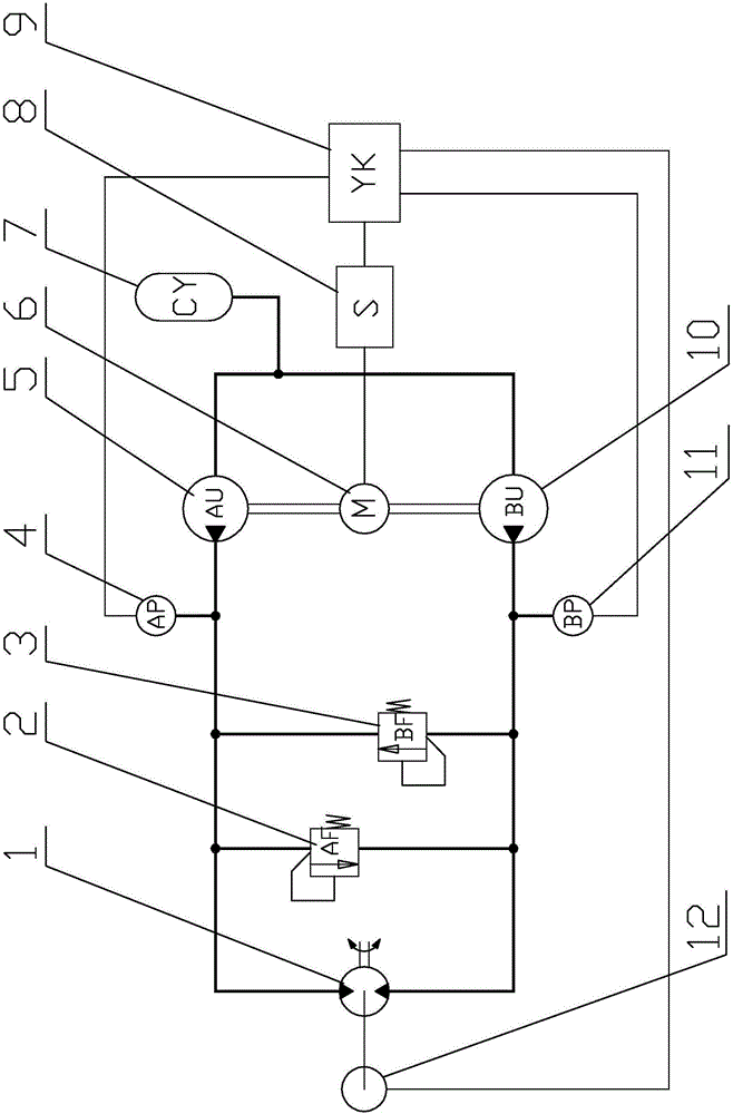
[0034] Embodiment 1 of the servo pump-controlled hydraulic rotary drive system is as follows: figure 1 As shown, the thick solid line connecting the components in the figure indicates the oil pipeline between the components, the thin solid line indicates the electrical connection between the electrical components, and the dotted line indicates the coupling between the angular displacement sensor and the hydraulic motor , the double solid line indicates the coupling between the shaft extension of the servo motor and the hydraulic pumps A and B.

[0035] A hydraulic pump 5 (shown as AU in the figure) and B hydraulic pump 10 (shown as BU in the figure) are both forward pumps, and their displacements are equal, and they are respectively connected to servo motor 6 (shown as M in the figure). Front axle extension and rear axle extension coupling. The liquid outlet of the A hydraulic pump 5 is connected to the forward oil inlet of the hydraulic motor 1 through the pipeline, and the ...

Embodiment 2

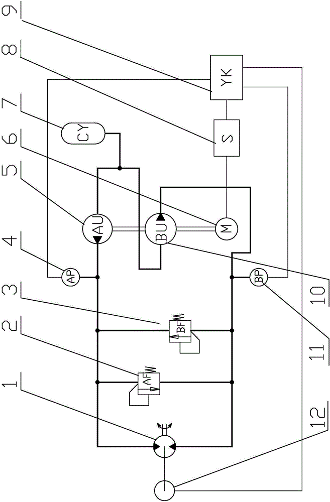
[0038] In this embodiment 2 such as figure 2 As shown, the A hydraulic pump 5 is a forward pump, and the B hydraulic pump 10 is a reverse pump, which are installed on the front axle of the servo motor 6 together. A liquid storage / accumulator 7 is also connected to the oil circuit connecting the A hydraulic pump 5 and the B hydraulic pump 10 , and the other structures of the second embodiment are the same as those of the first embodiment.

Embodiment 3

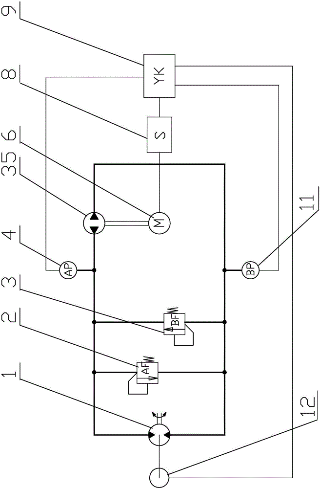
[0040] The present embodiment 3 such as image 3 As shown, the two-way pump 35 (DU shown in the figure) replaces the A hydraulic pump 5 and the B hydraulic pump 10 in the embodiment 1. The two-way pump 35 has an A oil outlet and a B oil outlet, respectively connected to the hydraulic pressure Forward oil inlet and reverse oil inlet of motor 1. When the servo motor 6 rotates forward, A of the two-way pump 35 outputs hydraulic oil to the oil outlet and B sucks hydraulic oil to the oil outlet. When the servo motor 6 reverses, B outputs hydraulic oil to the oil outlet while A The oil port sucks hydraulic oil. In this example, an oil supply valve or an oil supply port is installed on the oil circuit where the A-direction oil outlet and the B-direction oil outlet of the bidirectional pump 35 are connected to each other. When the oil leaks in the oil circuit, the oil supply valve or the oil supply port replenishes the oil circuit Hydraulic oil. Other structures of the third embodi...


PUM


Abstract

The invention provides a servo-pump-controlled hydraulic rotary driving system and a control method. According to the system, a hydraulic motor is connected with two hydraulic pumps which are connected with a servo motor and controlled by a servo driver and the servo motor. A motion control unit is connected with the servo driver and two pressure sensors arranged on a hydraulic motor connecting pipeline. An angular displacement sensor on the hydraulic motor is connected to the motion control unit. The control method includes the steps that the servo motor rotates positively and negatively to drive the pumps to rotate positively and negatively, and then the hydraulic motor is driven to rotate positively and negatively. The motion control unit precisely and quickly controls the angular displacement, the speed and the torque of the hydraulic motor according to set requirements and feedback of pressure and angular displacement. According to the servo-pump-controlled hydraulic rotary driving system and the control method, the high response frequency and high precision control of the hydraulic motor can be achieved, and wide-range gear ratio adjustment can be conveniently achieved. The servo-pump-controlled hydraulic rotary driving system is simple in structure, low in cost and reliable in control.

Description

technical field [0001] The invention relates to a hydraulic precision transmission control device, specifically a servo pump-controlled hydraulic rotary drive system and a control method. The invention uses a servo motor to drive two one-way pumps or one two-way pump, and then controls the power output of the hydraulic motor to realize High-precision and high-response rotary motion control. Background technique [0002] It is a commonly used power structure to control the rotary motion and power output through the hydraulic motor. The traditional hydraulic rotary drive system is a motor-driven hydraulic pump that runs continuously. The oil circuit composed of various valve groups, sensors and pipelines controls the flow of hydraulic oil. , flow rate, pressure, drive the hydraulic motor, and then realize the control of the external output torque and rotation speed of the hydraulic motor. In the traditional pump control system, when it is necessary to control the rotation spe...

Claims


Application Information

Patent Timeline
Patent Type & Authority Applications(China)
IPC IPC(8): F16H39/02F16H61/44
CPCF16H39/02F16H61/44
Inventor 吕爱群简飞
Owner 桂林星辰科技股份有限公司
Why Eureka
Try Eureka