Automatic pressure tapping device

An automatic and differential pressure technology, applied in the field of automatic pressure taking devices, can solve the problems of complicated pressure taking pipelines, complicated operations, inaccurate water pump simulation, etc., and achieve the effect of reducing the number of pipelines

Active Publication Date: 2017-05-24
ANHUI WANT AUTOMATION
View PDF7 Cites 1 Cited by
  • Summary
  • Abstract
  • Description
  • Claims
  • Application Information

AI Technical Summary

Problems solved by technology

Although this patent solves the problem of testing the characteristics of different types of valves, the pressure-taking pipeline is complicated, the operation is complicated, and the water pump simulation is inaccurate, which affects the accuracy of the entire experiment.

Method used


Image

  • Automatic pressure tapping device
  • Automatic pressure tapping device

Examples


Embodiment Construction

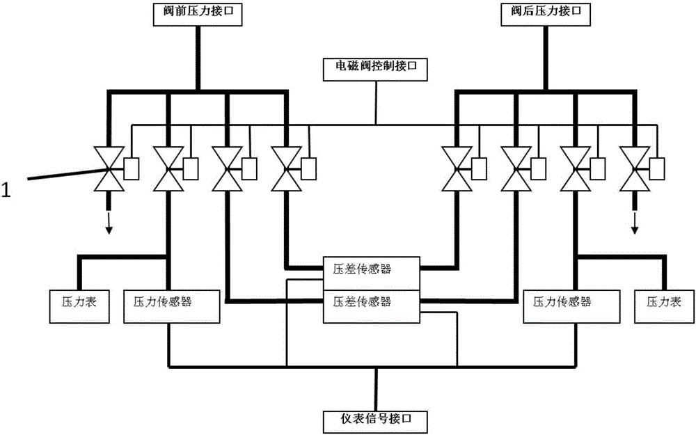
[0019] like figure 1 As shown, a pressure taking system in an automatic pressure taking device, the pressure taking system includes a pressure taking pipeline, a measuring instrument, a solenoid valve control interface, a solenoid valve group and an instrument signal interface, and the pressure taking pipeline and the solenoid valve control interface are respectively The input end of the electromagnetic valve group is connected, the output end of the electromagnetic valve group is connected to the measuring instrument, and the measuring instrument is connected to the instrument signal interface.

[0020] like figure 1 As shown, the pressure detection pipeline includes the pressure port before the valve and the pressure port after the valve. The pressure detection pipeline to be connected is designed as a set of pipeline system according to the requirements of use, and only the connection operation between the pressure port before the valve and the pressure port after the valve...


PUM


Abstract

The invention provides an automatic pressure tapping device, which comprises a cabinet body and a pressure tapping system arranged in the cabinet body, wherein the pressure tapping system comprises a pressure tapping pipeline, a measurement instrument, a solenoid valve control interface, a solenoid valve group and an instrument signal interface, wherein the pressure tapping pipeline and the solenoid valve control interface are respectively connected with the input end of the solenoid valve group; the output end of the solenoid valve group is connected with the measurement instrument; and the measurement instrument is connected with the instrument signal interface. the automatic pressure tapping device can move freely in a test area according to needs, the pressure tapping pipeline connection operation is simplified to the maximum degree, the pipeline and the cable number in the test area are simplified, the pressure tapping pipeline can be automatically controlled and switched according to a measurement instrument selected by a test person, and while the measurement data are observed in real time, the data are transmitted to a computer system in an electric signal mode.

Description

technical field [0001] The invention belongs to the technical field of truck air conditioners, and in particular relates to an automatic pressure taking device. Background technique [0002] Valve flow resistance test is a way to reduce valve flow resistance loss through product testing. The development of high-precision flow and flow resistance testing devices can provide reliable scientific data for valve product improvement and rational design of fluid engineering systems to reduce power consumption, select reasonable valves for industrial departments, and provide technical support for the development of new energy-saving products. The existing valve flow resistance test device is a high-precision and high-automation system designed for valve flow resistance test and supported by system software, covering detection, data acquisition, data processing and automatic control. In this system, the pre-valve pressure and post-valve pressure of the measured valve need to be conn...

Claims


Application Information

Patent Timeline
Patent Type & Authority Applications(China)
IPC IPC(8): G01M13/00
CPCG01M13/00
Inventor 王德荣朱晓华刘立周
Owner ANHUI WANT AUTOMATION
Why Eureka
Try Eureka