
Fluorescence detection system used for cell analyzer

A fluorescence detection and analyzer technology, applied in the field of fluorescence detection systems, can solve the problems of increased adjustment difficulty, high requirements on the positional accuracy of double prisms and optical fiber groups, etc., and achieves good cost advantages, good customer adaptability, and simple production process. Effect

Pending Publication Date: 2017-05-24
上海厦泰生物科技有限公司
View PDF6 Cites 4 Cited by
  • Summary
  • Abstract
  • Description
  • Claims
  • Application Information

AI Technical Summary

Problems solved by technology

The whole system has high requirements on the position accuracy of the double prism and the optical fiber group, which further increases the difficulty of adjustment of the whole system

Method used


Image

  • Fluorescence detection system used for cell analyzer
  • Fluorescence detection system used for cell analyzer
  • Fluorescence detection system used for cell analyzer

Examples


Embodiment Construction

[0037] The present invention will be further described in detail below through specific embodiments in conjunction with the accompanying drawings.

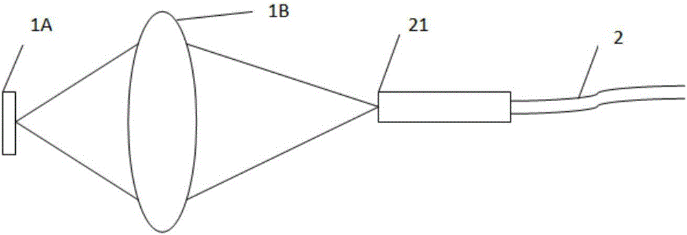
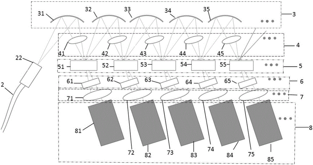
[0038] This fluorescence detection system for cell analyzers is characterized in that: the fluorescence detection system includes an objective lens 1B, an optical fiber 2, a concave mirror group 3, a cylindrical lens group 4, a beam splitter group 5, a band-pass Filter group 6, lens group 7 and detector group 8. The fluorescence detection system composed of the above components collects and detects the fluorescence emitted by the dyed sample particles passing through the detection area after being irradiated by laser light;

[0039] in:

[0040] The objective lens is used to collect and collimate the fluorescence generated after the sample particles are excited by the laser light;

[0041] The optical fiber includes an incident end face and an outgoing end face, and the optical fiber is used for transmitting fluorescence collimat...


PUM


Abstract

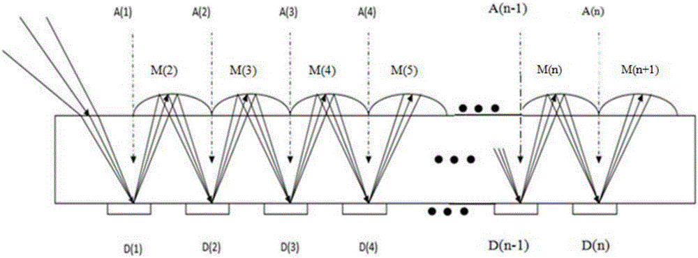
The invention discloses a fluorescence detection system used for a cell analyzer. The fluorescence detection system comprises an objective lens, an optical fiber, a concave mirror assembly, a cylindrical lens assembly, a spectroscope assembly, a band-pass filter assembly, a lens assembly, a detector assembly and the like. According to the fluorescence detection system disclosed by the invention, a multi-wavelength fluorescent signal is separated in space according to wavelength and is imaged on a detector in 1*magnification, and fluorescence analysis and determination are realized; the fluorescence detection system has the advantages of compact structure, small size, simple debugging and the like; and the wavelength and number of fluorescence during analysis and detection also can be flexibly adjusted according to the actual needs of customers.

Description

technical field [0001] The invention relates to the field of medical instruments, in particular to a fluorescence detection system for a cell analyzer. Background technique [0002] In the biological and medical fields, flow cytometers are often used to quantitatively count and analyze the types and quantities of biological cells. The flow cytometer uses fluorescent reagents to dye the sample. The dyed sample particles pass through the detection area, and at the same time, the laser beam is used to irradiate the detection area. Different types of dyed sample particles emit fluorescent signals of different wavelengths. These fluorescent signals of different wavelengths are mixed together are collected by the objective lens. At the same time, the fluorescence is divided into fluorescence signals of different wavelengths by using a spectroscope and a band-pass filter, and then these fluorescence signals of different wavelengths are analyzed one by one, and the types and quanti...

Claims


Application Information

Patent Timeline
IPC IPC(8): G01N21/64
CPCG01N21/6402G01N21/6486
Inventor 埃里克·蔡斯翟苏亚
Owner 上海厦泰生物科技有限公司
Learn More