Polarized light reuse imaging method and micro optical engine system based on optical wand

An optical engine, polarized light technology, applied in optics, instruments, projection devices, etc., can solve the problems of complex manufacturing process, small size of lens unit and polarization conversion device unit, difficult production and processing, etc., to achieve the effect of increasing size and cost

Inactive Publication Date: 2017-05-24
ZHEJIANG CRYSTAL DISPLAY TECH
View PDF9 Cites 10 Cited by
  • Summary
  • Abstract
  • Description
  • Claims
  • Application Information

AI Technical Summary

Problems solved by technology

Therefore, it is inevitable that half of the effective energy of the light energy after passing through the PBS is wasted, so that the light efficiency of the LCoS display system cannot achieve a satisfactory effect, but if the part that was originally wasted after passing through the PBS can be made When the polarized light of one polarization state is reused, the situation is quite different. Therefore, a reasonable method of polarized light multiplexing will solve this problem well and greatly improve the efficiency of illumination light.
[0004] Looking at the traditional polarization multiplexing methods, one of the more common ones is the polarization multiplexing micro-light engine system based on the compound eye, but the main problem is that the size of the lens unit of the compound eye and the polarization conversion device unit are too small. It is not easy to produce and process, which will not only make the polishing of the mold and PCS very difficult, but also cause the half-wave plate to be glued very difficult, and the polarized light multiplexing method based on birefringent crystals, due to the use of birefringent crystal blocks , but its manufacturing process is very complicated
As for other polarization multiplexing methods such as polarization interference filters and polymer polarization conversion films, its light conversion efficiency is not high.

Method used


Image

  • Polarized light reuse imaging method and micro optical engine system based on optical wand
  • Polarized light reuse imaging method and micro optical engine system based on optical wand
  • Polarized light reuse imaging method and micro optical engine system based on optical wand

Examples


Embodiment Construction

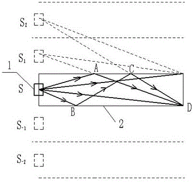
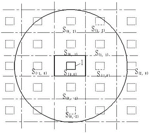
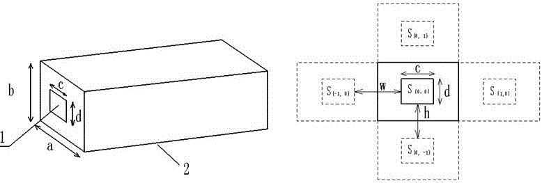
[0034] The traditional compound-eye polarized light multiplexing method uses the basic principle of the compound eye to split the wavefront of the plane wave to realize the beam splitting of the illumination light and complete the polarization conversion; while the polarization multiplexing method based on the cone-rod and 4F optical system does not exist to divide the illumination light The process of segmentation processing in advance will increase the caliber of the original lighting system to a certain extent. The invention mainly provides a polarized light multiplexing imaging method and a micro optical engine system based on an optical rod. The present invention realizes beam splitting and shaping of illumination light by combining non-imaging optics with imaging optics. On the premise that the caliber of the illumination system remains basically unchanged, the secondary imaging of the two-dimensional virtual light source array located at the front surface of the light ro...


PUM


Abstract

The invention discloses a polarized light reuse imaging method and a micro optical engine system based on an optical wand. Illuminating rays emitted by an LED illumination light source pass through the non-imaging optical element optical wand, a splitting lens and a polarized light conversion system to realize uniform light, beam splitting and shaping and polarized light conversion of the illuminating rays, and reaches an LCoS micro-display chip through collection and transfer of a follow-up relay system to form uniform illuminating spots; the illuminating spots illuminate an image on the LCoS micro-display chip to form a required image; and then, projection imaging is carried out on the image through a PBS polarizing prism, an imaging projection objective lens or an eye lens, wherein the optical wand serves as a generation source of a two-dimensional virtual light source array, the splitting lens carries out re-imaging on the two-dimensional virtual light source array formed at the front end of the optical wand, and the corresponding polarized light conversion system is added to a splitting surface of the illuminating rays to realize conversion of polarized light. The method can greatly improve light efficiency under the condition of basically not increasing size and cost of an original illumination system.

Description

technical field [0001] The invention belongs to the field of new display technologies, and in particular relates to a polarized light multiplexing imaging method based on an optical rod and a micro optical engine system. Background technique [0002] In recent years, with the rapid development of many technologies such as microelectronics, optics, and processing technology, modern business mobile office models have become popular, and handheld digital products have increased. Miniaturization has become a new direction for the development of new display technologies. The early micro-projection display technology in the new display field, as well as the VR and AR display technologies in the popular smart wearable display devices, are also developing rapidly. At present, micro-projection and high-resolution smart wearable micro-display technologies are mainly based on DLP (Digital Light Processor), LCoS (Liquid Crystal on Silicon), and OLED (Organic Light Emitting Display) tech...

Claims


Application Information

Patent Timeline
IPC IPC(8): G03B21/20
CPCG03B21/208G03B21/2033G03B21/206G03B21/2073
Inventor 张倩冯东洋周建军
Owner ZHEJIANG CRYSTAL DISPLAY TECH
Why Eureka
Try Eureka