An optical transmission window for atomic clocks

An optical transmission, atomic clock technology, applied in the field of atomic clocks, can solve the problem of batch coating of optical lenses, etc., and achieve the effects of ensuring coverage, reducing damage probability, and improving yield

Active Publication Date: 2022-07-22
NO 12 RES INST OF CETC
View PDF37 Cites 0 Cited by
  • Summary
  • Abstract
  • Description
  • Claims
  • Application Information

AI Technical Summary

Problems solved by technology

Through the improvement of the structure of the optical transmission window, the present invention is suitable for the batch coating needs of the optical transmission window, and solves the problem that the traditional optical transmission window cannot be coated with multiple optical transmission windows at the same time by the existing coating machine due to the limitation of its structure. The problem of batch coating of optical lenses in

Method used


Image

  • An optical transmission window for atomic clocks
  • An optical transmission window for atomic clocks
  • An optical transmission window for atomic clocks

Examples


Embodiment 1

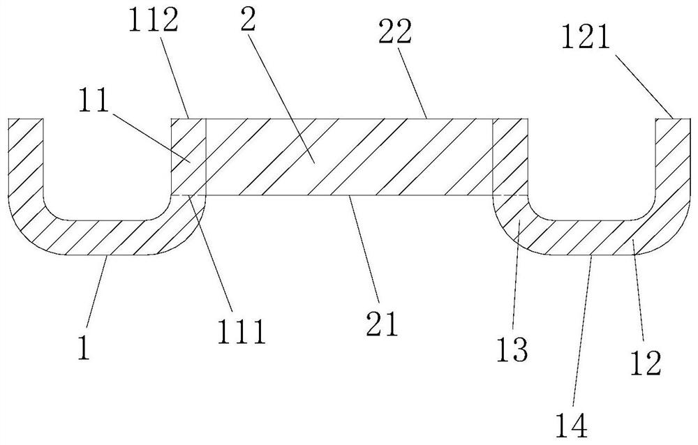
[0036] like figure 1 , 2 As shown, an optical transmission window for an atomic clock, the optical transmission window includes a sleeve 1 and an optical lens 2 arranged in the sleeve 1; the cylindrical wall of the sleeve 1 includes a vertical side wall portion 11, and an extension portion 12 located at the bottom end of the vertical side wall portion 11 and extending outward along the circumference of the bottom end of the vertical side wall portion 11; the extension portion 12 is Preferably, an arc-shaped transition portion 13 is provided between the vertical side wall portion 11 and the extension portion 12 . The end portion 121 of the extension portion 12 is the connection end where the optical transmission window and the metal shell of the vacuum atomic device are connected and fixed. Preferably, the cylindrical wall of the sleeve 1 is an integral structure.

[0037] The circumferential side wall surface of the optical lens 2 is sealed and fixed with the inner side wa...

Embodiment 2

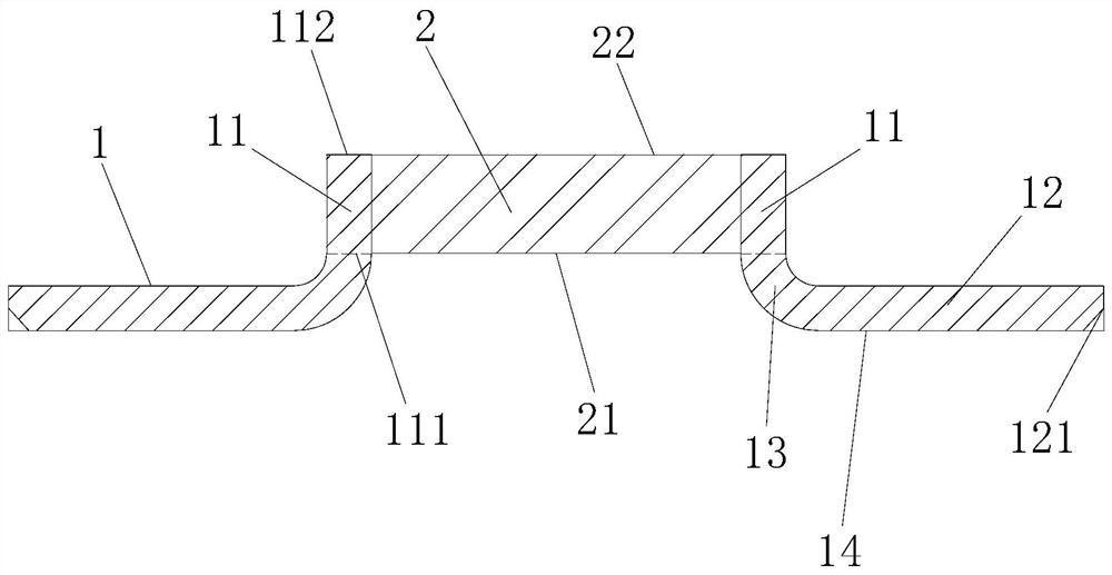
[0042] like image 3 As shown, an optical transmission window for an atomic clock, the optical transmission window includes a sleeve 1 and an optical lens 2 arranged in the sleeve 1; the cylindrical wall of the sleeve 1 includes a vertical side wall portion 11, and an extension portion 12 located at the bottom end of the vertical side wall portion 11 and extending outward along the circumference of the bottom end of the vertical side wall portion 11; the extension portion 12 is in an inline structure; preferably, An arc-shaped transition portion 13 is provided between the vertical side wall portion 11 and the extension portion 12 . The end portion 121 of the extension portion 12 is the connection end where the optical transmission window and the metal shell of the vacuum atomic device are connected and fixed. Preferably, the cylindrical wall of the sleeve 1 is an integral structure.

[0043] The circumferential side wall surface of the optical lens 2 is sealed and fixed with...

Embodiment 3

[0046] like Figure 4 As shown, an optical transmission window for an atomic clock, the optical transmission window includes a sleeve 1 and an optical lens 2 arranged in the sleeve 1; the cylindrical wall of the sleeve 1 includes a vertical side wall portion 11, and an extension portion 12 located at the bottom end of the vertical side wall portion 11 and extending outward along the circumference of the bottom end of the vertical side wall portion 11; the extension portion 12 is in a "shaped structure; preferably, An arc-shaped transition portion 13 is provided between the vertical side wall portion 11 and the extension portion 12 . The end portion 121 of the extension portion 12 is the connection end where the optical transmission window and the metal shell of the vacuum atomic device are connected and fixed. Preferably, the cylindrical wall of the sleeve 1 is an integral structure.

[0047] The circumferential side wall surface of the optical lens 2 is sealed and fixed wit...


PUM


Abstract

The invention discloses an optical transmission window for an atomic clock. The optical transmission window includes a sleeve and an optical lens set in the sleeve; a cylindrical wall of the sleeve includes a vertical side wall; The bottom end of the vertical side wall portion is an extension portion extending outward along the circumference of the bottom end of the vertical side wall portion; the circumferential side wall surface of the optical lens and the vertical side wall of the cylindrical body wall The inner side wall surface of the part is sealed and fixed; the bottom surface of the optical lens is flush with the bottom edge of the vertical side wall part in the barrel wall. By improving the structure of the optical transmission window, the invention is suitable for the batch coating of the optical transmission window, and solves the problem that the traditional optical transmission window cannot be used for multiple optical transmission windows at one time due to the limitation of its structure by the existing coating machine. The problem of batch coating of optical lenses in .

Description

technical field [0001] The present invention relates to the technical field of atomic clocks. More specifically, it relates to an optical transmission window for an atomic clock. Background technique [0002] Atomic clock is an instrument that uses atomic energy level transition to achieve high-precision time and frequency output. In order to maintain ultra-high vacuum, the shell of vacuum atomic devices is generally welded by metal. In the preparation of atomic energy levels and the excitation of atoms to make transitions, it is necessary to transmit a laser beam of a certain frequency into the vacuum atomic device to interact with the atoms. In order to miniaturize and meet engineering applications, optical metallization sealing is generally used. The transmission window is to coat the metallization layer on the side of the optical lens, and then use the brazing technology to weld the optical lens and the metal sleeve with solder (the melting point generally does not exc...

Claims


Application Information

Patent Timeline
Patent Type & Authority Patents(China)
IPC IPC(8): G04F5/14G02B7/00
CPCG02B7/007G04F5/14
Inventor 陈海军郑玥杨剑青刘忠征梁友焕李莉莉肖顺禄
Owner NO 12 RES INST OF CETC
Why Eureka
Try Eureka