A self-inductive anti-bird device
A bird-proof and bird-proof technology, applied in the field of self-induction bird-proof devices, can solve the problems of large damage to birds, unsuitable for large-scale promotion, etc., and achieve the effects of high sensitivity, ensuring safety, and protecting safety.
- Summary
- Abstract
- Description
- Claims
- Application Information
AI Technical Summary
Problems solved by technology
Method used
Image
Examples
Embodiment 1
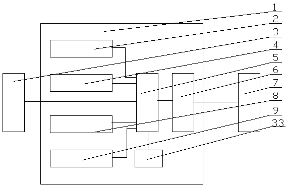
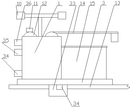
[0052] Such as figure 1 and figure 2 As shown: this embodiment provides a self-inductive anti-bird device, including an overhead track 13 arranged along the power transmission line, a moving trolley 3 set on the overhead track 13, a balance set on the bottom surface of the moving trolley 3 Mechanism 33, the inspection robot 1 set on the mobile trolley 3 and the control center 7 connected with the inspection robot 1, the bird detection module 2, the visual inspection module 4, the bird inspection module 1 are set on the inspection robot 1 Expulsion module 8, bird's nest removal module 9, control module 5 and communication module 6, described bird's nest removal module 19 comprises bird's nest picking mechanism 14 and bird's nest storage mechanism 15, described control module 5 and described mobile dolly 3, bird detection Module 2, visual inspection module 4, bird expelling module 8, bird's nest removal module 9 and communication module signal 6 are connected;
[0053] The ba...
Embodiment 2
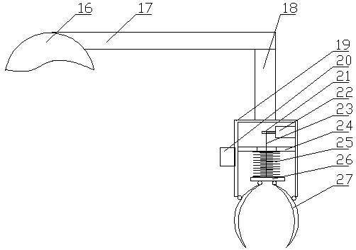
[0067] Such as image 3 and Figure 4 Shown: its difference with embodiment one is:
[0068] The bird's nest picking mechanism 14 includes a telescopic cross arm 17 arranged on the top of the inspection robot 1 through a rotating mechanism 16, a telescopic column 18 is arranged below the front end of the telescopic cross arm 17, and a hollow tube 19 is provided at the lower end of the telescopic column 18. The lower edge of the hollow tube 19 is evenly distributed with several arc-shaped claws 27, the arc-shaped claws 27 are connected to the lower edge of the hollow tube 19 in rotation, and the top ends of the arc-shaped claws 27 extend into the hollow tube 19 Inside, the top of the arc-shaped claw 27 is slidably connected with the connecting plate 26, and the center of the connecting plate 26 is connected with the driving motor 22 arranged on the upper part of the hollow tube 19 through a pull rope 23, and the pull rope 23 is wound around the On the rotating shaft 21 of the d...
Embodiment 3
[0073] The difference from Embodiment 2 is that the bird's nest storage mechanism 15 includes a cabinet 33 arranged behind the inspection robot 1 , an opening 37 is provided at the upper end of the cabinet 33 and an electric push-pull cover is provided corresponding to the opening 37 . The bird's nest storage mechanism is realized through the cabinet body, and an electric push-pull cover is set on the cabinet body to avoid the impact of strong wind and rain on the interior. The opening of the cabinet is at the upper end for putting in the bird's nest.
[0074] The electric push-pull cover plate comprises the chute 28 provided on both sides of the opening 37 at the upper end of the cabinet body 33, a slide block 29 is arranged in the chute 28, and a horizontal plate 30 is arranged on the slide block 29. Cabinet body 33 sides are provided with electric telescoping rod 31 on one side of described horizontal plate 30 sliding direction, and the end of described electric telescopic ...
PUM
 Abstract
Description
Claims
Application Information
 - R&D
- Intellectual Property
- Life Sciences
- Materials
- Tech Scout
- Unparalleled Data Quality
- Higher Quality Content
- 60% Fewer Hallucinations
Browse by: Latest US Patents, China's latest patents, Technical Efficacy Thesaurus, Application Domain, Technology Topic, Popular Technical Reports.
© 2025 PatSnap. All rights reserved.Legal|Privacy policy|Modern Slavery Act Transparency Statement|Sitemap|About US| Contact US: help@patsnap.com


