Method for obtaining target transmission path and network node thereof

A technology of network nodes and transmission paths, applied in the field of communications, can solve problems such as not very suitable, inherently insufficient path delay, and unable to ensure that the end-to-end delay of low-latency services does not exceed a certain threshold, and achieves the effect of improving reliability.

Active Publication Date: 2017-05-24
HUAWEI TECH CO LTD
View PDF5 Cites 34 Cited by
  • Summary
  • Abstract
  • Description
  • Claims
  • Application Information

AI Technical Summary

Problems solved by technology

[0003] Although the current IP or MPLS network has Quality of Service (QoS) technologies such as Differentiated Services (DiffServ for short), it can transmit traffic on the same path according to different QoS, or it can be based on QoS Different paths are used for transmission, but because it is essentially a packet multiplexing network, it is still unavoidable that high-priority packets will be queued or even blocked in the queue, causing the delay to exceed the threshold, and even in the In the worst case, packet loss occurs, and there is no guarantee that the end-to-end delay of the low-latency service stream during the actual forwarding process will not exceed a certain threshold
[0004] In the Internet Engineering Task Force (IETF for short), the intermediate system to intermediate system protocol (Intermediate System to Intermediate System, short for IS-IS), the shortest path first (Open Shortest Path First, short for OSPF) routing protocol has been Considering that the link delay is included in the routing measurement, none of them provide a specific link delay me

Method used


Image

  • Method for obtaining target transmission path and network node thereof
  • Method for obtaining target transmission path and network node thereof
  • Method for obtaining target transmission path and network node thereof

Examples


Embodiment Construction

[0056] The following will clearly and completely describe the technical solutions in the embodiments of the present invention with reference to the drawings in the embodiments of the present invention. Obviously, the described embodiments are part of the embodiments of the present invention, not all of them.

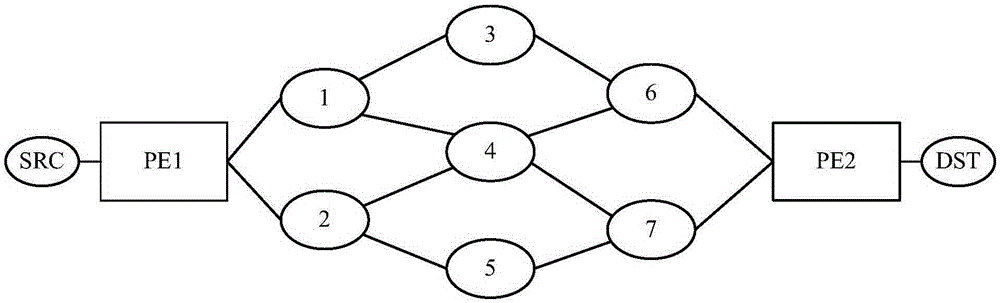
[0057] Multiple network nodes can be included in the IP / MPLS network, such as figure 1 as shown, figure 1 It can be regarded as a partial schematic diagram of a metropolitan area network, where the network domain can be a collection of all network nodes connected by physical topology and running the same routing protocol; and the network domain can support the routing implementation method described in the embodiment of the present invention . in such as figure 1 In the shown network domain, between PE1 and PE2 between the source end (Source, referred to as SRC) and the destination end (Destination, referred to as DST), there are multiple intermediate network nodes, th...


PUM


Abstract

The embodiment of the invention relates to a method for obtaining a target transmission path and a network node thereof. The method comprises the steps that the first network node in a network domain obtains topological information of multiple network nodes in each path between an entry node and an exit node in the network domain; the first network node obtains the transmission delay of each path according to the topological information, and the transmission delay of each path includes the sum of the physical link delay between all the network nodes in each path and node residence time of all the network nodes; and the first network node determines the target transmission path according to the transmission delay of each path. According to the method for obtaining the target transmission path and the network node thereof, transmission of low delay business in the network is ensured to meet the delay requirements, and multiple low delay paths between the entry node and the exit node in the network can be more fully utilized so as to enhance the transmission reliability of the low delay business.

Description

technical field [0001] The present invention relates to the communication field, in particular to a method and a network node for obtaining a target transmission path. Background technique [0002] Network protocol (Internet Protocol, referred to as IP) or multi-protocol label switching (Multi-Protocol Label Switching, referred to as MPLS) network generally needs to support low-latency traffic, for example: the low-latency requirements of mobile bearer traffic above the fourth generation (4G) , such as the X2 interface requires less than or equal to 10ms (defined by 3GPP), although the communication bandwidth of the X2 interface only accounts for 2-5% of the total bandwidth of the mobile communication, but its delay requirement is very high. Another example: Although the monitoring information and commands of the smart grid do not require high bandwidth, they will continue continuously and require low-latency and high-reliability transmission in the network, otherwise the gr...

Claims


Application Information

Patent Timeline
IPC IPC(8): H04L12/727H04L45/121H04L45/02H04L47/56
CPCH04L45/121H04L45/70H04L45/02H04L43/106H04L47/56H04L43/0852H04L45/123
Inventor 江元龙朱恒军查敏
Owner HUAWEI TECH CO LTD
Why Eureka
Try Eureka