

Inertial air circulation valves for compressors of internal combustion engines
A technology for air circulation valves and compressors, applied to internal combustion piston engines, combustion engines, machines/engines, etc., can solve problems such as small thermal load capacity, expensive plastics, and difficult disassembly, so as to reduce fouling, avoid losses, cost reduction effect
Active Publication Date: 2019-10-01
PIERBURG GMBH & CO KG NEUSS
View PDF6 Cites 0 Cited by
- Summary
- Abstract
- Description
- Claims
- Application Information
AI Technical Summary
Problems solved by technology
Although this simplifies the installation, it has the result that gas can penetrate from the housing interior space into the laterally connected channels through the gaps between the parts
This air flow can also lead to the infiltration of contaminated gases into the gap, which leads to agglomeration, which obviously makes the disassembly of the valve difficult.
In addition, the plastics used are also prone to increased fouling due to their lower thermal load capacity
Alternatively, very expensive plastics must be used
Method used
View moreImage
Smart ImageViewing Examples

Examples
Embodiment Construction
Login to View More PUM
 Abstract
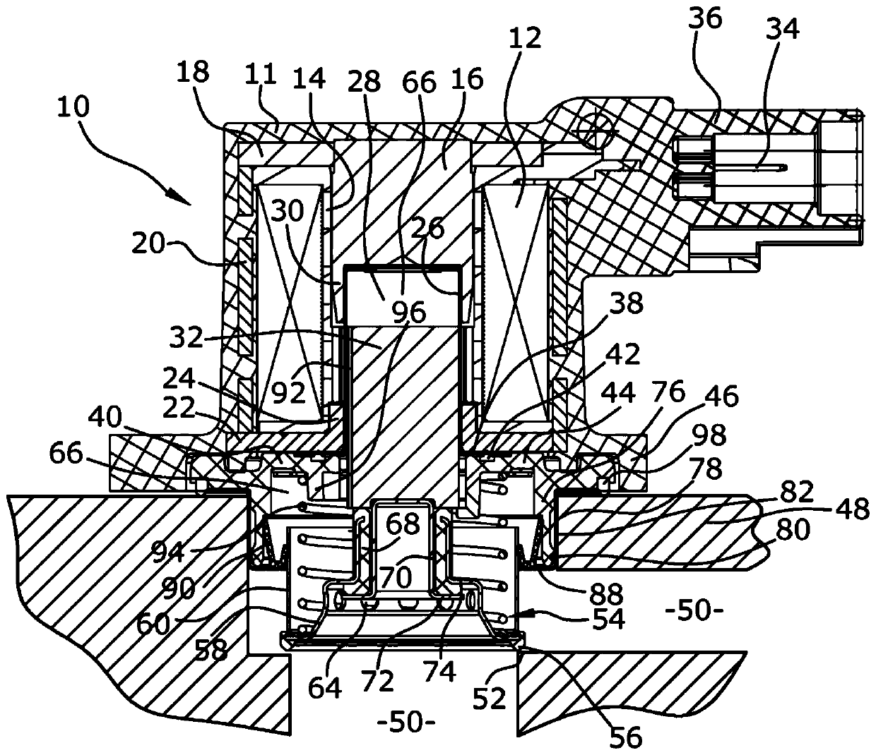
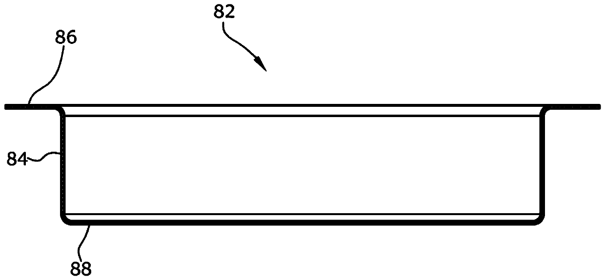
The invention relates to an inertial air circulation valve for a compressor of an internal combustion engine, comprising a fluid housing (48), an electromagnetic actuator (10), a regulating body (54), a housing interior (66), the Openings ( 64 ) in the regulating body ( 54 ), valve housings ( 11 , 40 ) and radial sealing rings ( 90 ), in which passages ( 50 ) are formed in the fluid housing, the regulating body ( 54 ) by means of an actuator ( 10 ) The flow cross-section of the channel ( 50 ) is movable and adjustable by means of an adjusting body, in the housing interior ( 66 ), the armature ( 32 ) of the electromagnetic actuator ( 10 ) connected to the adjusting body ( 54 ) Movable, opening (64) in the adjusting body (54), through the opening (64) of the housing interior space (66) and the part of the channel (50) that rests axially on the adjusting body (54) in the fluid Fluidly connected in the housing (48), the valve housing (11, 40) radially surrounds the electromagnetic actuator (10) and the axially extending section of the regulating body (54), via radial sealing rings (90), The housing interior ( 66 ) is sealed against the part of the channel ( 50 ) which rests radially on the adjusting body ( 54 ) and the radial sealing ring ( 90 ) is supported axially in the radial direction of the bearing ring ( 82 ). On the inwardly directed annular plate ( 88 ), the bearing ring rests radially from the outside with a cylindrical wall ( 84 ) against the housing wall ( 76 ) of the valve housing ( 11 , 40 ). In order to obtain a cost-effectively producible valve with increased tightness between the two channel parts to be separated, it is proposed here that the radial sealing ring ( 90 ) abuts the valve housing ( 11 ) radially outwards , 40) on the housing wall (76).
Description
technical field The invention relates to an inertial air circulation valve for a compressor of an internal combustion engine, which has a flow housing, an electromagnetic actuator, an adjusting body, an interior space of the housing, an opening in the adjusting body, a valve housing, a radial sealing ring, a channel is formed in the flow housing, the adjusting body is movable by means of an actuator and the flow cross-section of the channel can be adjusted by means of the adjusting body, in the housing interior, the The armature of the electromagnetic actuator, which is connected to the adjusting body, is movable, and through the opening, the housing interior is fluidically connected to the part of the channel which rests axially on the adjusting body in the flow housing, so that The valve housing radially surrounds the electromagnetic actuator and the axially extending section of the adjusting body, and the inner space of the housing rests against the adjusting body radially r...
Claims
Login to View More Application Information
Patent Timeline
 Patent Type & AuthorityPatents(China)
IPC IPC(8): F02B37/16
CPCF16K27/029F16K1/36F16K1/46F16K31/0655F16K31/0686F02B37/16Y02T10/12F16K31/0644
InventorM.伦克O.保罗
OwnerPIERBURG GMBH & CO KG NEUSS