
Internal combustion engine

A technology for internal combustion engines and connecting rods, applied in mechanical equipment, engine components, engine control, etc., to solve problems that cannot be said to have been fully researched

Active Publication Date: 2017-05-24
NISSAN MOTOR CO LTD
View PDF5 Cites 5 Cited by
  • Summary
  • Abstract
  • Description
  • Claims
  • Application Information

AI Technical Summary

Problems solved by technology

[0005] However, as a multi-link piston-crank mechanism, various structures have been considered, and it cannot be said that sufficient research has been conducted on the lubrication of the sliding portion of each of the above-mentioned structures. Partial lubrication has room for improvement

Method used


Image

  • Internal combustion engine
  • Internal combustion engine
  • Internal combustion engine

Examples


Embodiment Construction

[0015] Hereinafter, an embodiment of the present invention will be described in detail based on the drawings.

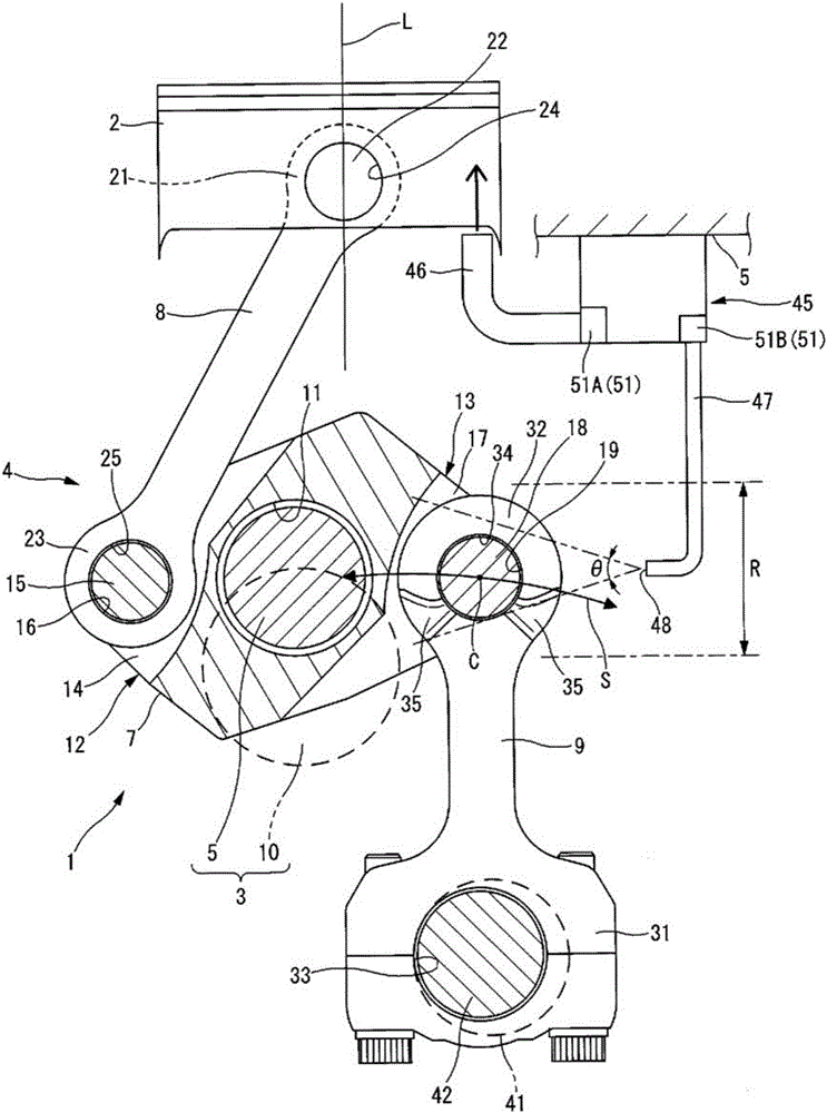
[0016] figure 1 It is an explanatory diagram schematically showing an example of the internal combustion engine 1 according to the present invention, and is an explanatory diagram corresponding to a cross section of the internal combustion engine 1 viewed from the crankshaft axial direction.

[0017] The internal combustion engine 1 has a multi-link piston crank mechanism 4 that connects a piston 2 and a crankshaft 3 by a plurality of connecting rods. The multi-link piston crank mechanism 4 in this embodiment is a variable compression engine capable of changing the compression ratio of the internal combustion engine by changing the top dead center position of the piston 2 reciprocating in the cylinder (not shown) of the cylinder block 5 . than institutions.

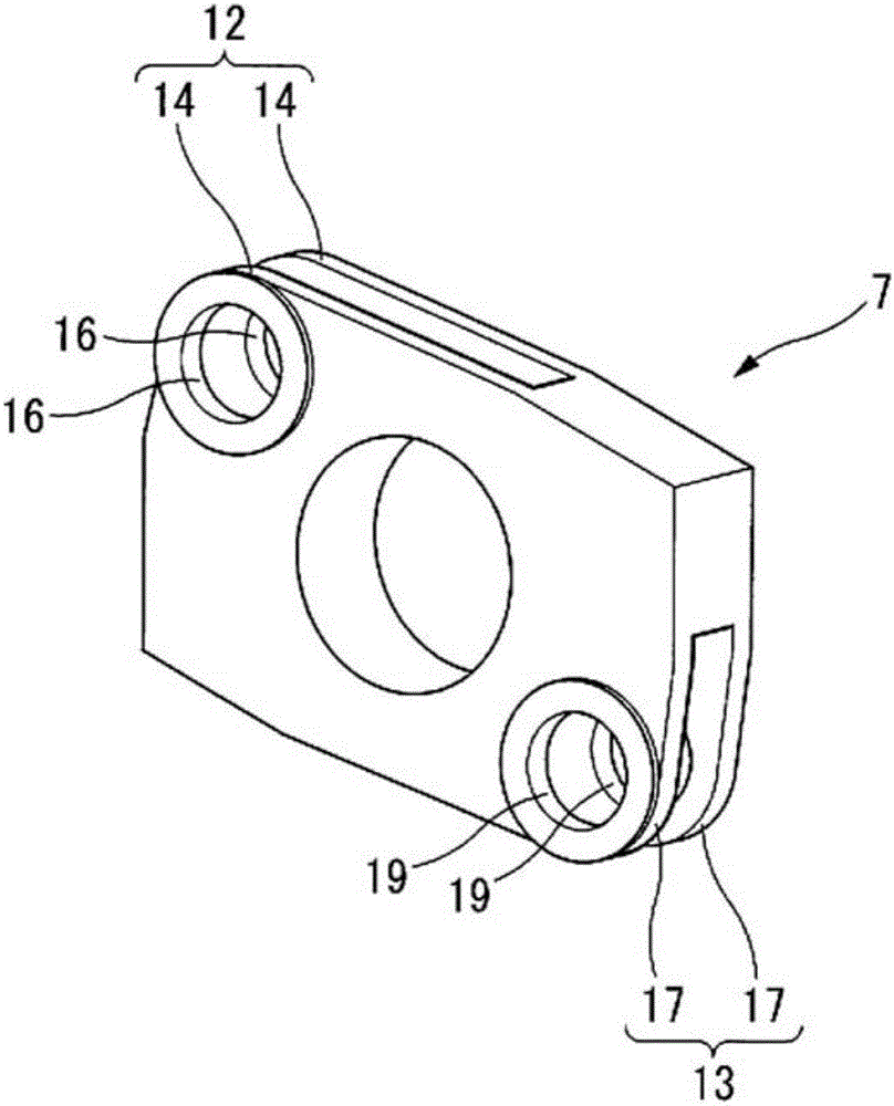
[0018] The multi-link piston crank mechanism 4 has: a lower connecting rod 7, which is rotatably mounted on...


PUM


Abstract

An oil jet (45) is provided in each cylinder in the lower part of a cylinder block (5). The oil jet (45) has a first injection nozzle (46) that injects lubricating oil toward the back of a piston (2) when a pressure control valve (51A) opens and a second injection nozzle (47) that injects lubricating oil toward the connection part of a lower link (7) and a control link (9) from the side of the control link (9), which is a direction perpendicular to the axis of a crankshaft, when a pressure control valve (51B) opens. Because of these features, lubricating oil can be continuously supplied to the connecting portions of the lower link (7) and the control link (9).

Description

technical field [0001] The invention relates to an internal combustion engine with a multi-link piston crank mechanism. Background technique [0002] Patent Document 1 discloses a variable piston stroke type internal combustion engine, which has: a connecting rod whose upper end is connected to the piston; an intermediate arm whose one end is connected to the crankshaft and the other end is connected to the lower end of the connecting rod; and a control rod, one end of which is connected to the intermediate arm, and the other end is movably connected to the moving mechanism as a swing center, and the movement of the intermediate arm is restricted to control the stroke amount of the piston. [0003] In this Patent Document 1, the fuel injector is arranged at the lower end of the cylinder, and the fuel injector can cool and lubricate the piston, the cylinder, the swing center of the other end of the control rod and the moving mechanism, wherein the fuel injector has: 1 inject...

Claims


Application Information

Patent Timeline
Patent Type & Authority Applications(China)
IPC IPC(8): F02B75/04F01M1/08F02B75/32F02D15/02
CPCF02B75/32F02D15/02F01P3/08F02B75/045F01M9/108F01P2007/146F01M1/08F01M1/06F01M2001/066F01P7/14F02B75/048
Inventor 黑田雅士田边孝司
Owner NISSAN MOTOR CO LTD
Learn More