Power inductor and method for manufacturing same

A technology of power inductors and manufacturing methods, applied in the field of power inductors

Active Publication Date: 2017-05-24
MODA INNOCHIPS CO LTD
View PDF8 Cites 9 Cited by
  • Summary
  • Abstract
  • Description
  • Claims
  • Application Information

AI Technical Summary

Problems solved by technology

However, in the power inductor, since the external electrode is disposed on the upper part of the power inductor, the power inductor may form a short circuit with the shield case

Method used


Image

  • Power inductor and method for manufacturing same
  • Power inductor and method for manufacturing same
  • Power inductor and method for manufacturing same

Examples


Embodiment Construction

[0046] Hereinafter, specific embodiments will be described in detail with reference to the accompanying drawings. This disclosure may, however, be embodied in many different forms and should not be construed as limited to the embodiments set forth herein. Rather, these embodiments are provided so that this disclosure will be thorough and complete, and will fully convey the concept of the invention to those skilled in the art.

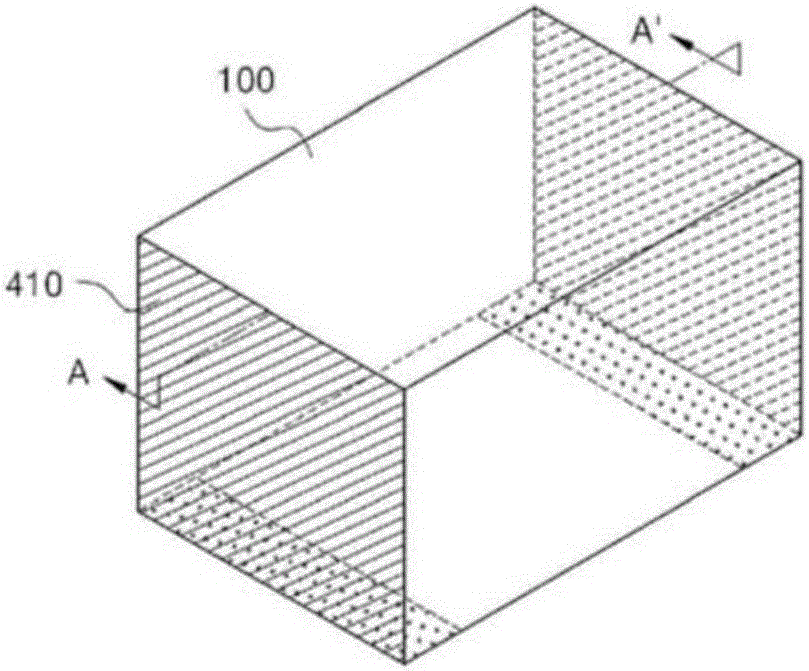
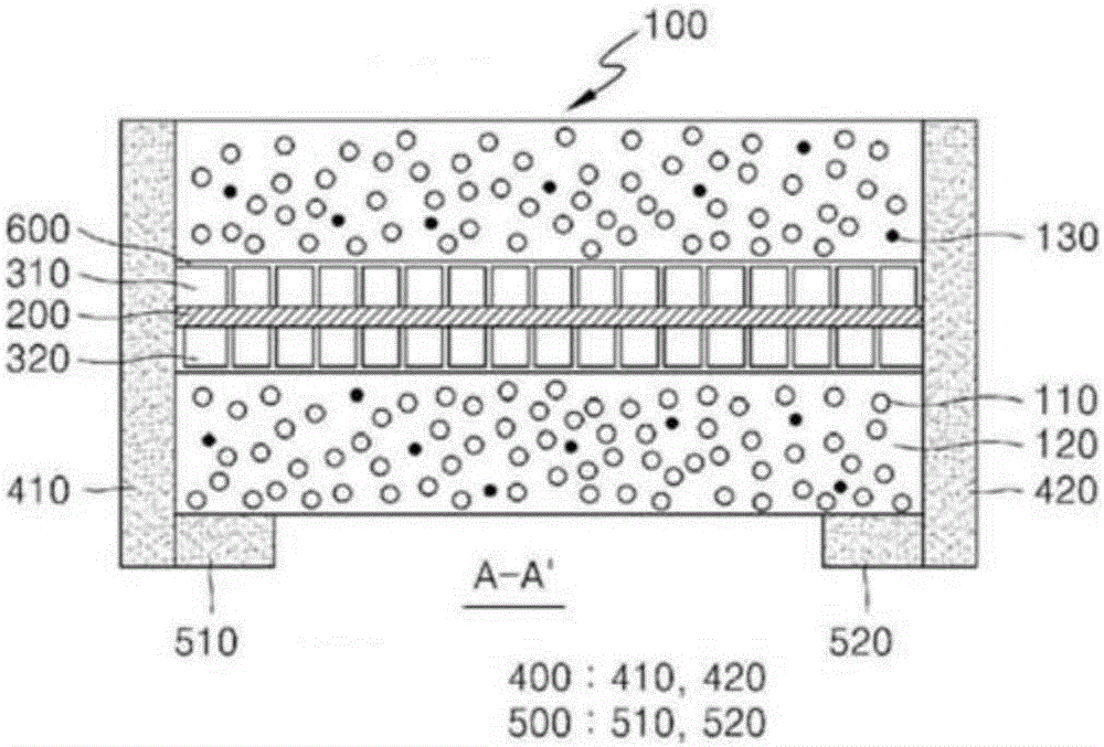
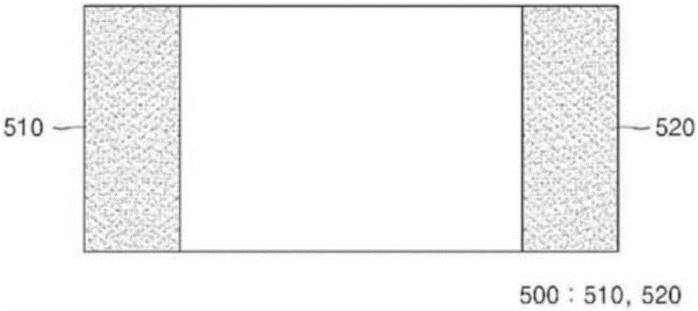
[0047] figure 1 is a perspective view of a power inductor according to the first embodiment, figure 2 for along figure 1 A cross-sectional view taken along the line A-A' of , and image 3 for figure 1 A plan view of the bottom surface of .

[0048] see Figure 1 to Figure 3 , the power inductor according to the first embodiment may include: a main body (100); at least one substrate (200), which is disposed in the main body (100); coil patterns (310, 320; 300), which are disposed on the substrate (200) ) on at least one surface; a first external el...


PUM

PropertyMeasurementUnit
particle sizeaaaaaaaaaa

Abstract

Provided in the present invention are a power inductor and a method for manufacturing same, the power inductor comprising: a body; a substrate provided inside the body; a coil formed on top of the substrate; first external electrodes which are connected to the coil and provided on the sides of the body; and second external electrodes which are connected to the first external electrodes and provided on the bottom surface of the body.

Description

technical field [0001] The present disclosure relates to a power inductor, and more particularly, to a power inductor capable of preventing short circuits with peripheral devices and a method of manufacturing the same. Background technique [0002] Power inductors are generally provided on power circuits such as DC-DC converters provided in portable devices. Due to the trend toward high frequency and miniaturization of power circuits, power inductors are increasingly being used to replace existing wound-type choke coil patterns. Also, miniaturized, high-current, and low-resistance power inductors are being developed because small and multifunctional portable devices are required. [0003] Power inductors can be fabricated in the form of stacked bodies of ceramic sheets formed from various ferrites or low-k dielectrics. Here, a metal pattern is formed on each of the ceramic sheets in a coil pattern shape. The coil patterns formed on the ceramic sheets are connected to each...

Claims


Application Information

Patent Timeline
Patent Type & Authority Applications(China)
IPC IPC(8): H01F17/00H01F17/02H01F27/28H01F41/04B22F1/102B22F1/16
CPCH01F17/0013H01F17/04H01F2017/048H01F27/22C09K5/14H01F27/292B22F1/16B22F1/102H01F17/02H01F27/2804H01F41/043H01F2027/2819H01F27/008H01F2027/2809B22F3/02B22F2301/35B22F2302/25B22F2302/45B29C43/02B29C65/002B29L2031/34C08K3/04C08K3/08C08K3/22C08K3/28C08K2003/0856C08K2003/222C08K2003/282C08K2201/001C08K2201/01C23C18/1637C23C18/1653C25D7/123H01F27/34H01F41/0233H01F41/041H01F41/10H05K1/181H05K2201/1003
Inventor 朴寅吉金炅泰赵承勳郑俊镐南基正李政圭
Owner MODA INNOCHIPS CO LTD
Why Eureka
Try Eureka