Tractor tool management and control method

A management control, tractor technology, applied in the field of tractors, can solve the problems of reducing operating efficiency, tractor or implement damage, complicated operation, etc., and achieve the effects of improving operating efficiency, avoiding damage, and simplifying operations

Active Publication Date: 2017-05-31
LOVOL HEAVY IND
View PDF7 Cites 5 Cited by
  • Summary
  • Abstract
  • Description
  • Claims
  • Application Information

AI Technical Summary

Problems solved by technology

[0003] At present, when the operator lifts and lowers the machine tool, he usually closes or combines the power output and turns the machine tool by manual operation. The operation is relatively complicated, and there is a possibility of damage to the tractor or machine tool due to misoperation.
[0004] In the prior art, there is also a structure in which the power output is disconnected when the operator operates the lifting handle through a mechanical linkage swit

Method used


Image

  • Tractor tool management and control method
  • Tractor tool management and control method
  • Tractor tool management and control method

Examples


Embodiment 1

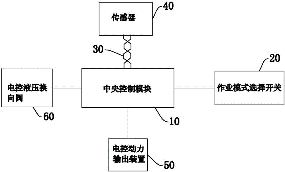
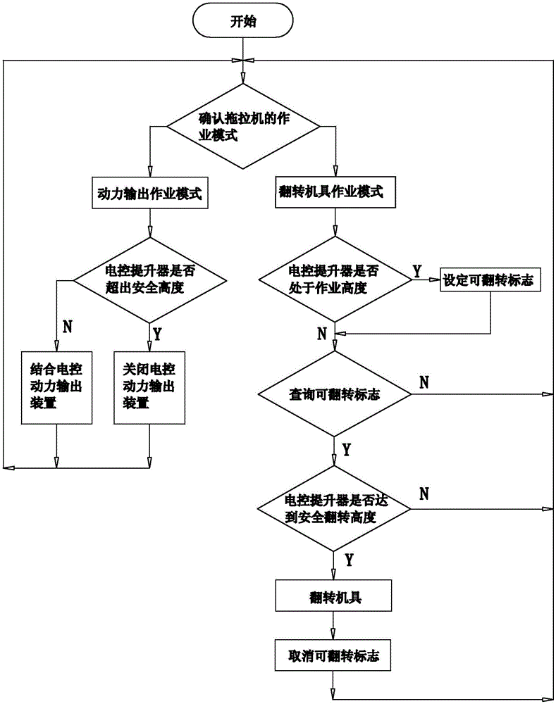
[0026] Such as figure 1 and figure 2 Commonly shown is a tractor implement management control method, based on the electronic control system and the height data of the electronic control lifter detected by the sensor, the tractor's electronically controlled power output device and the electronically controlled hydraulic reversing valve of the turning implement are controlled.

[0027] The electronic control system includes a connected central control module 10 and an operation mode selection switch 20; the central control module 10 is an independent controller or integrated in the electronic control unit of the tractor vehicle; the operation mode selection switch 20 is used as an electronic control The input of the system is not limited in form and quantity, it can be keys, buttons or human-computer interactive touch screen and so on.

[0028] In this embodiment, the electronic control lifter itself is equipped with a sensor 40 that can measure the height, and the central co...

Embodiment 2

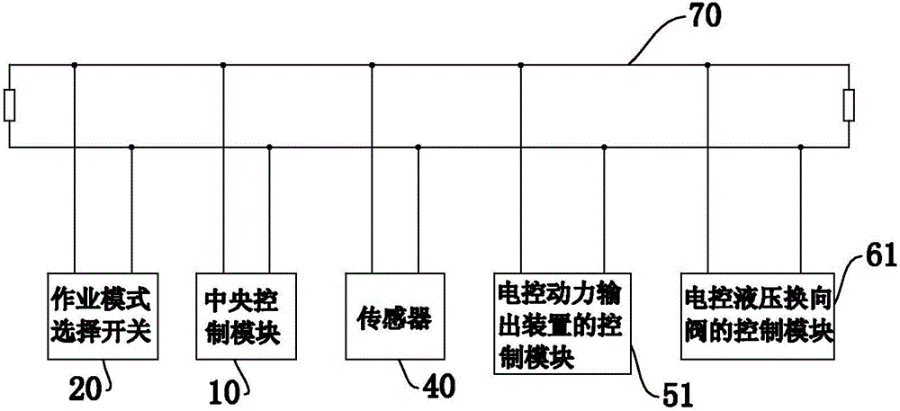
[0037] This embodiment is basically the same as Embodiment 1, the difference is that, as image 3 As shown, the central control module 10, the operation mode selection switch 20, the sensor 40, the control module 51 of the electronically controlled power output device and the control module 61 of the electronically controlled hydraulic reversing valve are in the same bus network.

[0038] The central control module 10 indirectly controls the control module 51 of the electronically controlled power output device and the control module 61 of the electronically controlled hydraulic reversing valve through the bus 70 .

[0039] The bus 30 and the bus 70 can be CAN bus or other forms of bus.

[0040] The tractor implement management control method provided by the present invention automatically closes or combines the power output device and flip implement based on the height of the lifter, without manual control, simplifies the operation of the operator, improves the working effici...


PUM


Abstract

The invention discloses a tractor tool management and control method, and belongs to the technical field of tractors. The method is used for controlling an electronic control power output device and an electronic control hydraulic reverse valve on the basis of an electronic control system and height data of an electronic control lifter. The method comprises the following steps that an operation mode selection switch is operated, a power output operation mode is activated, when the electronic control lifter exceeds the preset power output safe height, the electronic control power output device is powered off, and when the electronic control lifter is in a safe height range, the electronic control power output device is combined; the operation mode selection switch is operated, a turning tool operation mode is activated, and when the electronic control lifter rises to the safe turning height from the operation height range, the electronic control hydraulic reverse valve conducts reversing, and then a turning tool conducts turning. According to the tractor tool management and control method, the power output device and the turning tool are automatically powered off or combined on the basis of the height of the lifter, manual control is not needed, operation of a manipulator is simplified, the operation efficiency is improved, and damage caused by misoperation of the manipulator to the tool or a tractor power output shaft is avoided.

Description

technical field [0001] The invention belongs to the technical field of tractors, and in particular relates to a management and control method for tractor implements. Background technique [0002] In tractor farmland operations, if the implement is connected to the power take-off shaft, the operator will often turn off the power output when lifting the implement to prevent damage to the tractor power take-off shaft or implement universal joint. When the implement is lowered to a safe working height Then recombine the power output for operation; if the implement is a hydraulic reversing plow, when the end of the row is lifted to a safe reversing height, it is necessary to turn the hydraulic reversing plow over through the hydraulic reversing valve to meet the operation needs of the next row. [0003] At present, when lifting and lowering the implements, the operator usually closes or combines the power output and flips the implements manually. The operation is relatively compl...

Claims


Application Information

Patent Timeline
IPC IPC(8): A01B71/02A01B63/02
CPCA01B63/02A01B71/02
Inventor 李泉明王进邢来章王静
Owner LOVOL HEAVY IND
Why Eureka
Try Eureka