Lens module and eye base imaging device with same

A technology of lens modules and imaging equipment, which is applied in the direction of eye testing equipment, ophthalmoscopes, applications, etc., can solve poor imaging quality, cannot eliminate axial chromatic aberration and vertical axis chromatic aberration, and cannot effectively eliminate axial chromatic aberration of the eyepiece lens and vertical axis chromatic aberration to achieve good imaging effect

Active Publication Date: 2017-05-31
SHANGHAI MEDIWORKS PRECISION INSTR CO LTD
View PDF10 Cites 9 Cited by
  • Summary
  • Abstract
  • Description
  • Claims
  • Application Information

AI Technical Summary

Problems solved by technology

However, this technology uses a single-piece aspheric lens as the eyepiece lens, which can neither effectively eliminate the axial chromatic aberration and vertical axis chromatic aberration of the eyepiece lens itself, nor can it eliminate the axial chromatic aberration and vertical axis chromatic aberration of the combined system including the human eye and the eyepiece lens. Chromatic aberration, system image quality is poor

Method used


Image

  • Lens module and eye base imaging device with same
  • Lens module and eye base imaging device with same
  • Lens module and eye base imaging device with same

Examples


Embodiment 1

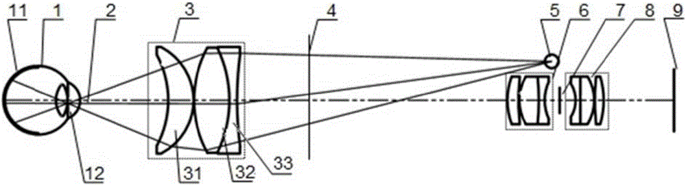
[0054] There is an existing lens module for fundus imaging, the layout of which can be found in figure 1 shown. The lens system includes a first lens module 3 , a second lens module 6 , an imaging aperture stop 7 and a third lens module 8 from the fundus side to the final image plane. The overall effective focal length of the first lens module 3 is positive, and consists of two groups of three lenses. The first lens 31 is a positive focal length lens, and its side facing the eye 1 to be inspected is concave, and the other side is convex. The second lens 32 and the third lens 33 are double-glued structures, the surface nearest to the eye 1 to be inspected is convex, and the surface farthest is concave. The second lens module may include one or more lenses. The overall effective focal length of the third lens module is positive, and may include one or more lenses.

[0055] When the above-mentioned lens module is used for imaging the fundus 11, in order to illuminate the fund...

Embodiment 2

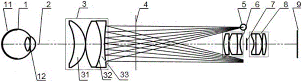
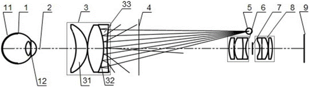
[0064] There is an existing lens module for fundus imaging, the layout of which can be found in image 3 shown. The lens system includes a first lens module 3 , a second lens module 6 , an imaging aperture stop 7 and a third lens module 8 from the fundus side to the final image plane. The overall effective focal length of the first lens module 3 is positive, and consists of two groups of three lenses. The first lens 31 and the second lens 32 are a double glued structure, the surface closest to the eye 1 to be inspected is concave, and the surface farthest is convex. The third lens 33 is a single-piece positive focal length lens with a convex surface facing the eye 1 to be examined and a concave surface on the other side. The second lens module 6 may include one or more lenses. The overall effective focal length of the third lens module 8 is positive, and may include one or more lenses.

[0065] When the above-mentioned lens module is used for imaging the fundus 11, in orde...


PUM


Abstract

The invention provides a lens module. The effective focal length of the lens module is a positive value, the lens module comprises a first lens, a second lens and a third lens which are mutually fitted, the first lens is a positive focal length lens, the side surface of the first lens close to an eye to be detected is a concave surface, the side surface of the first lens far away from the eye to be detected is a convex surface, the second lens and the third lens are of gluing structures, the side surface of the second lens close to the eye to be detected is a convex surface, and the side surface of the third lens far away from the eye to be detected is a concave surface. Compared with the prior art, the lens module has the advantages that a first lens module can effectively compensate axial and vertical axis color difference of the eye to be detected, an imaging plane of the lens module has better imaging effect, the lens close to one side of the eye to be detected is a concave surface, the curvature radius of the surface is properly set, and obvious stray light cannot be introduced into imaging results even if the surface has smudge.

Description

technical field [0001] The invention relates to a lens module of a fundus camera and a fundus photographic device composed of the lens module. Background technique [0002] The fundus camera is a traditional medical device, which is used to observe and record the retinal images of the human eye, and provide objective basis for doctors to analyze and diagnose. The only capillaries that can be directly observed in the human body are distributed on the retina detected by the fundus camera. The changes in the shape of these capillaries can be used for early diagnosis of fundus diseases, hypertension, diabetes and other diseases, and have become an important means of modern medical diagnosis. . The world's first desktop fundus camera was successfully trial-produced by the German CARLZEISS company in 1925. Subsequently, CANON, TOPCON, NIKON, OLYMPUS, OPTON and other companies made a lot of improvements to the design of the fundus camera. Now the desktop camera on the market Full...

Claims


Application Information

Patent Timeline
Patent Type & Authority Applications(China)
IPC IPC(8): A61B3/12A61B3/14A61B3/15G02B13/00G03B15/02
CPCA61B3/0008A61B3/12A61B3/14A61B3/15G02B13/00G03B15/02
Inventor 杨丛渊陈文光郭丁华赵立秀魏悦赵小飞皮晓奔
Owner SHANGHAI MEDIWORKS PRECISION INSTR CO LTD
Why Eureka
Try Eureka