Dust removal and heat exchange all-in-one treatment device and method for high temperature dusty flue gas

A processing device and flue gas technology, applied in chemical instruments and methods, combustion methods, separation methods, etc., can solve problems such as restricting application and development, insufficient heat exchange, and materials that are not resistant to high temperature, so as to overcome low purification efficiency, The effect of sufficient heat exchange and not easy to accumulate dust

Active Publication Date: 2017-05-31
UNIV OF SCI & TECH BEIJING
View PDF5 Cites 3 Cited by
  • Summary
  • Abstract
  • Description
  • Claims
  • Application Information

AI Technical Summary

Problems solved by technology

The waste heat of flue gas in industry accounts for a large part of the heat, among which the emission of high-temperature flue gas is the largest heat loss item. In metallurgy, petrochemical, building materials, electric power and other industries, high-temperature dust-laden gas is often produced. However, the current high-temperature dust-laden gas There are a series of defects in the recycling equipment and methods. The reason is that under high temperature conditions, the lack of heat exchange equipment and dust removal equipment restricts its application and development.
[0003] For the traditional heat exchanger, when dealing with dusty flue gas, the heat exchange tube is easy to accumulate dust, which affects its heat exchange efficiency and service life. In addition, it also has the disadvantages of small specific surface area and insufficient heat exchange.
For dust removal equipment, under high temperature conditions, due to the large change in viscous force, the aggregation of fine particles is greatly reduced, so it is more difficult to separate the particles. In addition, there are materials that are not resistant to high temperatures and work The disadvantage of discontinuity, due to the defect of dust removal equipment, the problem of environmental pollution caused by the failure of flue gas dust removal to meet the standard is also becoming more and more serious

Method used


Image

  • Dust removal and heat exchange all-in-one treatment device and method for high temperature dusty flue gas

Examples


Embodiment 1

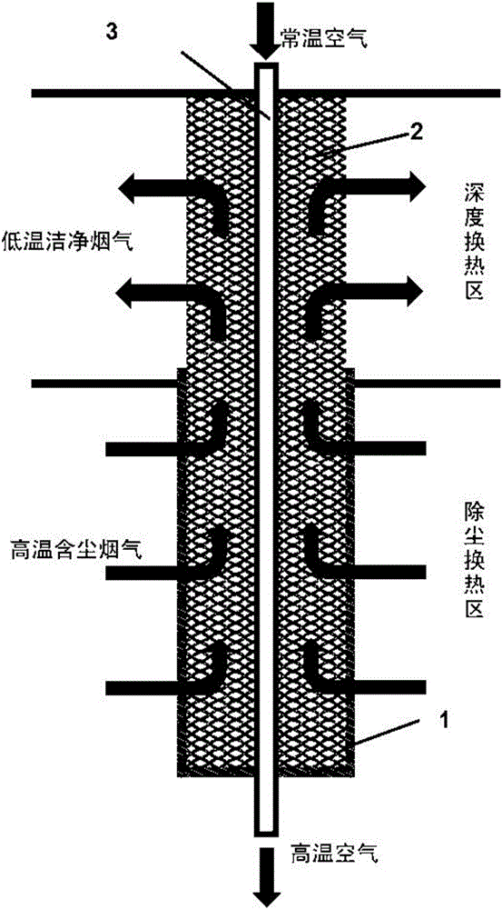
[0031] An integrated treatment method for dust removal and heat exchange for high-temperature dusty flue gas. The high-temperature dusty flue gas enters the device from the flue gas inlet, the temperature of the imported flue gas is 800°C, and the flow rate is 1000Nm 3 / h, the concentration of dust particles in the flue gas is 2000mg / Nm 3 , the dust particle size range is about 1.0μm-70μm, the flue gas passes through the metal filter membrane 1 to block the dust particles outside the metal filter membrane 1, and the flue gas after dust removal enters the upper box and exchanges heat with the heat exchange tube 3 in countercurrent. The flue gas passes through the metal honeycomb skeleton 2 inside the metal filter membrane 1 to enhance heat exchange, and the flue gas after heat exchange flows out of the equipment through the flue gas outlet. The air enters the heat exchange tube 3 from the inlet, and the flow rate is 850Nm 3 / h, the inside of the heat exchange tube 3 runs throu...

Embodiment 2

[0033] An integrated treatment method for dust removal and heat exchange for high-temperature dusty flue gas. The high-temperature dust-laden flue gas enters the device from the flue gas inlet, the temperature of the imported flue gas is 1000°C, and the flow rate is 1000Nm 3 / h, the concentration of dust particles in the flue gas is 2000mg / Nm 3 , the particle size range of dust particles is about 30μm-100μm, the flue gas passes through the metal filter membrane 1 to block the dust particles outside the metal filter membrane 1, the flue gas after dust removal enters the upper box, and exchanges heat with the heat exchange tube 3 countercurrently, the smoke The gas passes through the metal honeycomb skeleton 2 inside the metal filter membrane 1 to enhance heat exchange, and the flue gas after heat exchange flows out of the equipment through the flue gas outlet. The air enters the heat exchange tube 3 from the inlet, and the flow rate is 850Nm 3 / h, the inside of the heat excha...


PUM

PropertyMeasurementUnit
Particle sizeaaaaaaaaaa

Abstract

The invention provides a dust removal and heat exchange all-in-one treatment device and method for high temperature dusty flue gas, and belongs to the technical field of industrial energy conservation and environmental protection. The device consists of a dust removal and heat exchange pipe, wherein the dust removal and heat exchange pipe comprises a metal filter membrane, a metal honeycomb framework and a heat exchange pipe; an upper box body of a box body where the dust removal and heat exchange pipe is located is a deep heat exchange region, and a lower box body of the box body is a dust removal and heat exchange region; in the lower box body, the heat exchange pipe penetrates through the metal honeycomb framework and is covered with the dense metal filter membrane; and in the upper box body, the heat exchange pipe penetrate through the metal honeycomb framework and is not covered with the dense metal filter membrane. The high temperature dusty flue gas passes through the dust removal and heat exchange region and the deep heat exchange region from bottom to top, and air passes through the heat exchange pipe from top to bottom. The method realizes a breakthrough in continuous dust removal and heat exchange integration for the high temperature dusty flue gas with the temperature of 800 DEG C or above; the heat recycling efficiency can be up to 90 percent, and the dust removal efficiency can be up to 99 percent; and the dust removal and heat exchange all-in-one treatment device has the advantages of efficient purification, full heat exchange, continuous work, difficulty in ash deposition and the like.

Description

technical field [0001] The invention relates to the technical field of industrial energy saving and environmental protection, in particular to an integrated dust removal and heat exchange treatment device and method for high-temperature dust-laden flue gas. Background technique [0002] With the rapid development of economy, my country's energy consumption has increased rapidly, while the energy utilization rate has only remained at a low level. The waste heat of flue gas in industry accounts for a large part of the heat, among which the emission of high-temperature flue gas is the largest heat loss item. In metallurgy, petrochemical, building materials, electric power and other industries, high-temperature dust-laden gas is often produced. However, the current high-temperature dust-laden gas There are a series of defects in the recovery equipment and method, the reason is that under high temperature conditions, the lack of heat exchange equipment and dust removal equipment ...

Claims


Application Information

Patent Timeline
IPC IPC(8): B01D46/54B01D46/42F23J3/02F23L15/00F28F1/44
CPCB01D46/543F23J3/02F23L15/00F28F1/44B01D46/76Y02E20/34
Inventor 夏德宏曲恒宇刘向军蒋滨繁
Owner UNIV OF SCI & TECH BEIJING
Why Eureka
Try Eureka