
A manufacturing method for electron beam rapid prototyping

A manufacturing method and electron beam technology, applied in the directions of additive manufacturing, process efficiency improvement, additive processing, etc., can solve the problems of reducing the dimensional accuracy of formed parts, destroying the electron gun, unable to form, etc., to avoid powder collapse and beam spot change. , the effect of good surface quality

Active Publication Date: 2019-01-18
XIAN ZHIRONG METAL PRINTING SYST CO LTD
View PDF7 Cites 0 Cited by
  • Summary
  • Abstract
  • Description
  • Claims
  • Application Information

AI Technical Summary

Problems solved by technology

The scattering of this kind of metal powder will lead to failure of forming, burning through the substrate, and even damage to equipment such as electron guns.
For this reason, it is necessary to use preheated and large-grained metal powder to manufacture parts to overcome the unfavorable phenomenon of powder flying, which will lead to reduced dimensional accuracy of formed parts
[0006] Therefore, it is urgent to find a rapid prototyping manufacturing method that can prevent metal powder from flying and overcome the difficulty of focusing to ensure processing accuracy.

Method used


Image

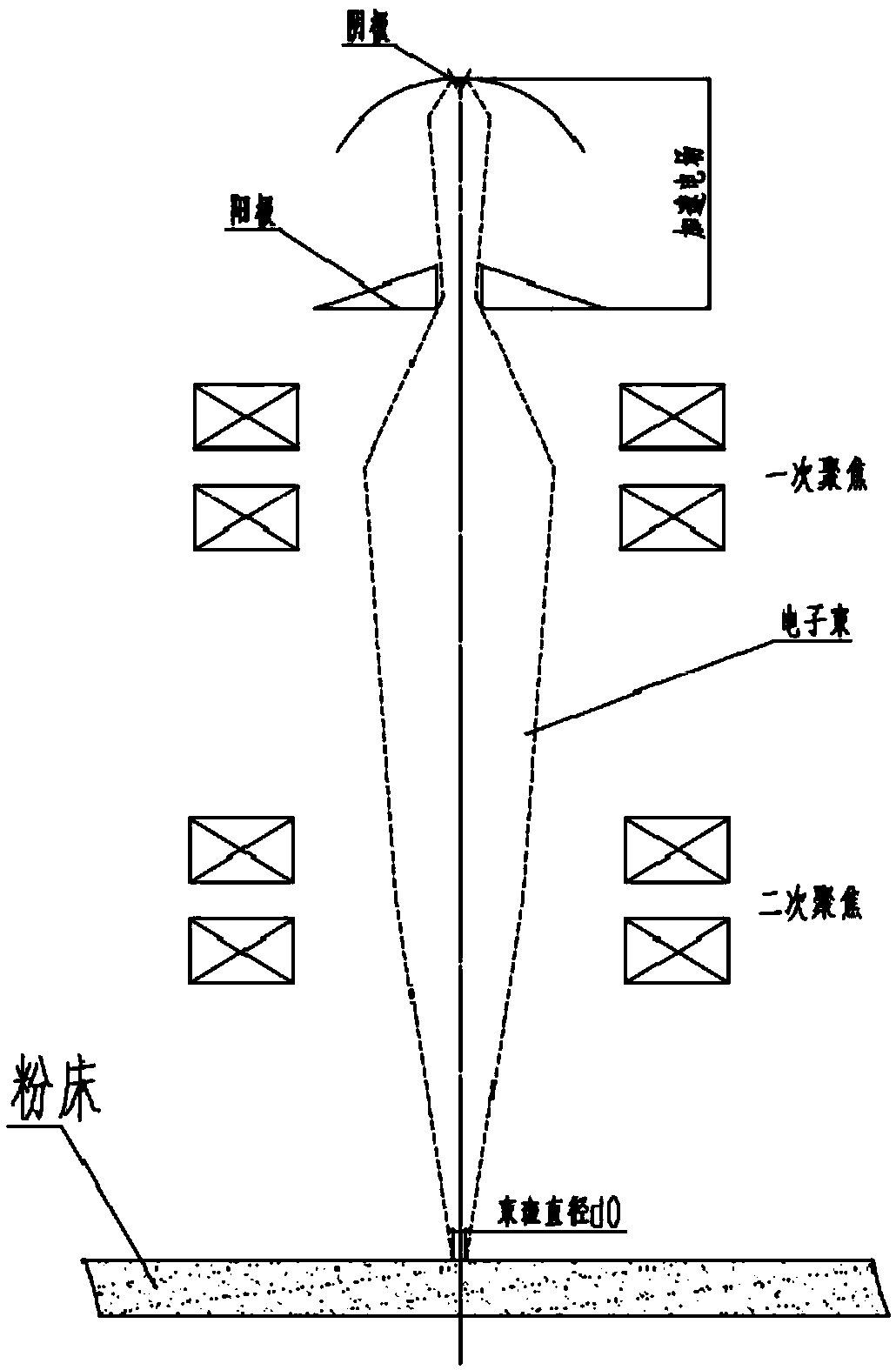
  • A manufacturing method for electron beam rapid prototyping
  • A manufacturing method for electron beam rapid prototyping
  • A manufacturing method for electron beam rapid prototyping

Examples


Embodiment Construction

[0022] In order to make the purpose, technical solution and advantages of the present invention clearer, the present invention will be further described in detail below in conjunction with the accompanying drawings and embodiments. It should be understood that the specific embodiments described here are only used to explain the present invention, not to limit the present invention.

[0023] According to the working principle of the electron gun, the higher the acceleration voltage, the smaller the effect of the initial thermal velocity of electrons on the beam spot size after focusing, that is, the higher the acceleration voltage, the smaller the beam spot diameter after focusing. For powder rapid prototyping, obtaining a small beam spot diameter is the key to ensure the dimensional accuracy and surface quality of the formed parts. Generally, in order to obtain better surface quality and dimensional accuracy of metal forming parts, a higher accelerating voltage is usually used...


PUM


Abstract

The present invention relates to the field of rapid prototyping manufacturing, in particular to an electron beam rapid prototyping manufacturing method. According to the requirements of the powder bed forming process, parameters such as the average particle diameter D0 of the metal powder, the diameter of the beam spot d0 and the value of the beam current Pb are determined through analysis and calculation. The scientific and reasonable output acceleration voltage effectively controls the speed of electron bombardment of metal powder, thereby avoiding the problem of powder collapse while ensuring the forming requirements; at the same time, due to the multi-level focusing method, it can improve and control the low acceleration voltage zone. The focus of the electron beam is difficult to achieve, and the electron beam spot is smaller and controllable; thus, it is possible to use finer metal powder than the existing electron beam rapid prototyping equipment to obtain metal with better surface quality and higher dimensional accuracy Parts; the present invention selects the size of the beam spot diameter and the particle size of the powder material according to the characteristics and technical requirements of different parts, which can improve the forming efficiency and reduce the production cost of the formed parts.

Description

technical field [0001] The invention relates to the field of rapid prototyping manufacturing, in particular to an electron beam rapid prototyping manufacturing method. Background technique [0002] Additive manufacturing technology is also known as 3D printing or rapid prototyping technology. It is a technology based on three-dimensional digital model files, using materials such as metal powder, wire or bondable plastics, to construct objects by stacking and accumulating layer by layer. Rapid prototyping manufacturing technology is widely used in mold making, industrial design and other fields, and it is gradually being used in the direct manufacturing of some products, especially some high-value applications (such as hip joints or teeth, or some aircraft parts). [0003] The rapid prototyping manufacturing methods of metal parts mainly include laser selective sintering (SLS), laser selective melting (SLM), laser coaxial powder feeding direct manufacturing (LENS), electron ...

Claims


Application Information

Patent Timeline
Patent Type & Authority Patents(China)
IPC IPC(8): B22F3/105B33Y10/00
CPCB33Y10/00B22F10/00B22F12/44B22F10/28Y02P10/25
Inventor 郭光耀
Owner XIAN ZHIRONG METAL PRINTING SYST CO LTD
Learn More