Automatic cutting machine

A cutting machine and automatic technology, which is applied in the direction of shearing devices, shearing machine accessories, shearing machine equipment, etc., can solve the problems of low cutting precision, excessive damage of cutting machine impact force, low degree of automation, etc., and achieve reduction Noise and service life of equipment, improvement of production efficiency and safety, and high degree of automation

Active Publication Date: 2017-05-31
青岛瑞宜利特变压器设备有限公司
View PDF6 Cites 13 Cited by
  • Summary
  • Abstract
  • Description
  • Claims
  • Application Information

AI Technical Summary

Problems solved by technology

[0002] At present, the equipment and processing technology used for cutting silicon steel sheets are outdated. The feeding and conveying mechanism of silicon steel strips uses conveying rollers to feed materials. Usually, the feeding length of silicon steel strips is measured according to the conveying rollers. Because the conveying rollers There will be a relative displacement between the silicon steel strip and the driving, which will lead to an error in the cutting position of the subsequent cutting unit on the silicon steel strip, the cutting accuracy is not high, and there will be some waste products
It is difficult for the old cutting equipment to ensure that the silicon steel material belt is transported forward along the forward direction during the material belt conveying process. The angle of the silicon steel material belt to both sides exceeds the specified range, which will cause The precision of the cut sheet is low, and the reject rate is extremely high
[0003] In addition, the existing silicon steel sheet cutting equipment uses an air cylinder or a hydraulic cylinder as the power to drive the blade to perform a punching movement to cut off the silicon steel strip to obtain a silicon steel sheet. This method will cause too much damage to the cutting machine itself. It will lead to the service life and production cost of the cutting blade, and at the same time affect the cutting accuracy of the sheet, resulting in high mechanical noise, resulting in high noise on the production site and affecting the health of operators
Due to the low degree of automation and backward production technology of the existing obsolete cutting equipment, the precision of the products obtained is not high, more waste is generated, and the production efficiency is low, resulting in high production costs.
Due to the mutual cooperation between the feeding conveying mechanism and the cutting unit, continuous production is realized. The existing cutting equipment lacks safety protection devices. In the case of a failure in a certain part, the equipment cannot stop running in time, resulting in damage and waste to the silicon steel strip.

Method used


Image

  • Automatic cutting machine
  • Automatic cutting machine
  • Automatic cutting machine

Examples


Embodiment 1

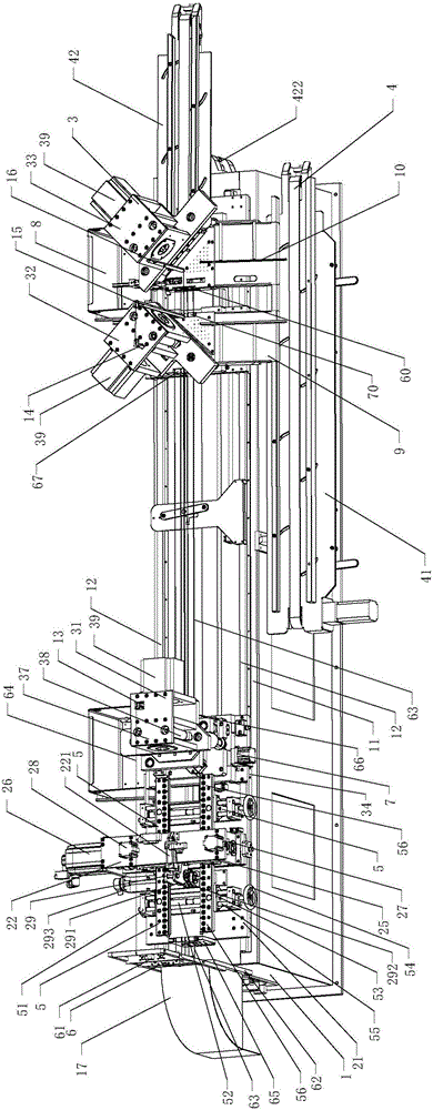
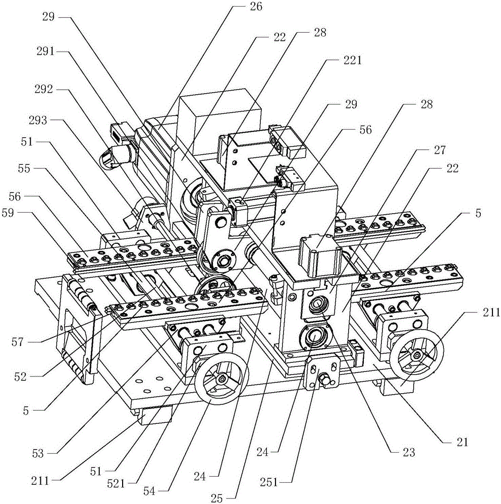
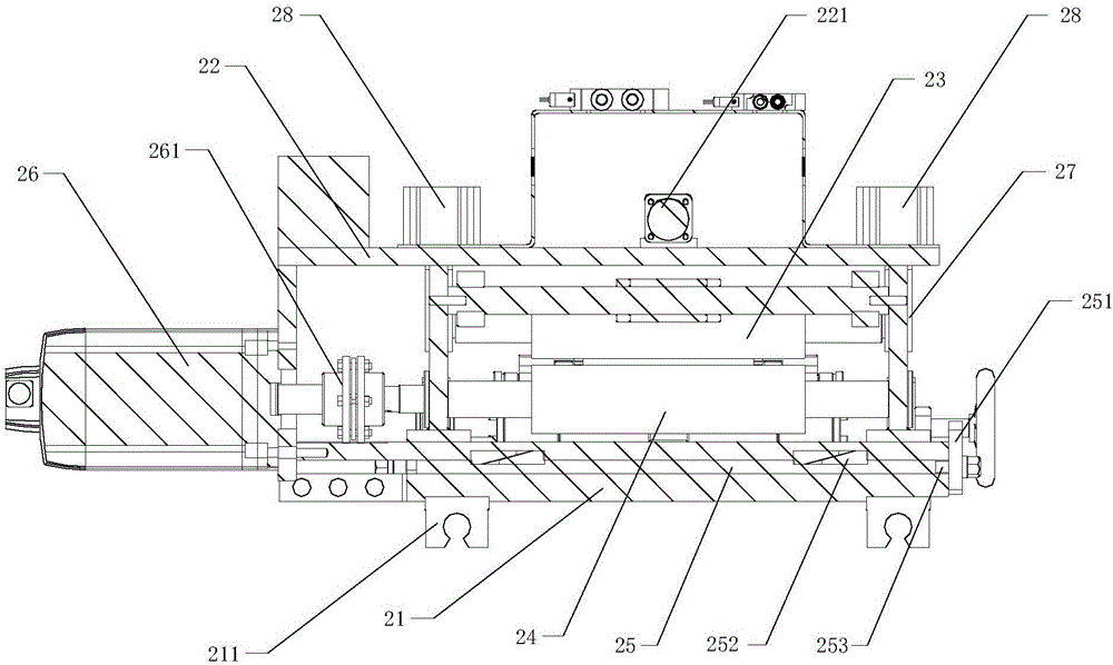
[0030] Embodiment 1, combining Figure 1 to Figure 11 , an automatic cutting machine, comprising an underframe 1, a feeding mechanism 2, a cutting unit 3 and a conveying device 4, a platform 11 is arranged above the underframe 1, guide rails 12 are respectively arranged on both sides of the platform 11, two guide rails 12 Parallel to each other, extending from the rear end of the platform 11 to its front end, the guide rail 12 is fixedly installed on the upper surface of the platform 11 through the guide rail seats located at its two ends. The feeding mechanism 2 is located above the rear of the platform 11, and the four corners below the large bottom plate 21 at the bottom are respectively equipped with sliding seats 211, and the large bottom plate 21 is slidably connected with the guide rail 12 through the sliding seats 211. The feeding mechanism 2 includes Feeding bracket 22, upper pressure roller 23 and lower pressure roller 24, adjusting plate 25 is arranged between the b...


PUM


Abstract

The invention discloses an automatic cutting machine. The automatic cutting machine comprises a bottom frame, a feeding mechanism and cutting units. A platform is arranged on the bottom frame. The two sides of the platform are provided with guide rails correspondingly. The feeding mechanism is located on the rear portion of the platform. A large bottom plate at the lower end of the feeding mechanism is in sliding connection with the guide rails. The feeding mechanism comprises a feeding bracket, an upper press roll and a lower press roll. The bottom of the feeding bracket is fixedly connected with the large bottom plate. The upper press roll and the lower press roll are vertically arranged on the feeding bracket. The lower press roll is driven by a first servo motor installed on one side of the feeding bracket. The front side and the rear side of the feeding mechanism are provided with material clamping mechanisms correspondingly. The three cutting units comprise the first cutting unit, the second cutting unit and the third cutting unit and are arranged on the guide rails from back to front in sequence. Through the cutting units of the cutting machine, impact force to a machine tool is decreased, equipment noise is lowered, the cutting precision is high, and the cutting machine is suitable for cutting sheets of various models; and the amount of cutting waste is small, the automation degree is high, and the production efficiency and safety are greatly improved.

Description

technical field [0001] The invention relates to the technical field of mechanical equipment, in particular to an automatic cutting machine. Background technique [0002] At present, the equipment and processing technology used for cutting silicon steel sheets are outdated. The feeding and conveying mechanism of silicon steel strips uses conveying rollers to feed materials. Usually, the feeding length of silicon steel strips is measured according to the conveying rollers. Because the conveying rollers There will be a relative displacement between the silicon steel strip and the silicon steel strip due to the drive, resulting in an error in the cutting position of the subsequent cutting unit for the silicon steel strip, the cutting accuracy is not high, and certain waste products appear. It is difficult for the old cutting equipment to ensure that the silicon steel material belt is transported forward along the forward direction during the material belt conveying process. The ...

Claims


Application Information

Patent Timeline
Patent Type & Authority Applications(China)
IPC IPC(8): B23D33/00B23D33/02B23D15/04
CPCB23D15/04B23D33/006B23D33/02
Inventor 袁媛
Owner 青岛瑞宜利特变压器设备有限公司
Why Eureka
Try Eureka