Bottom mold fixture device for metallographic sample automatic grinding and polishing machine
A metallographic sample and fixture device technology, applied in surface polishing machine tools, grinding/polishing equipment, preparation of test samples, etc. problems, to achieve the effect of convenient processing, installation and layout, ensuring the quality of grinding and polishing, and ensuring the quality of grinding and polishing
- Summary
- Abstract
- Description
- Claims
- Application Information
AI Technical Summary
Problems solved by technology
Method used
Image
Examples
Embodiment 1
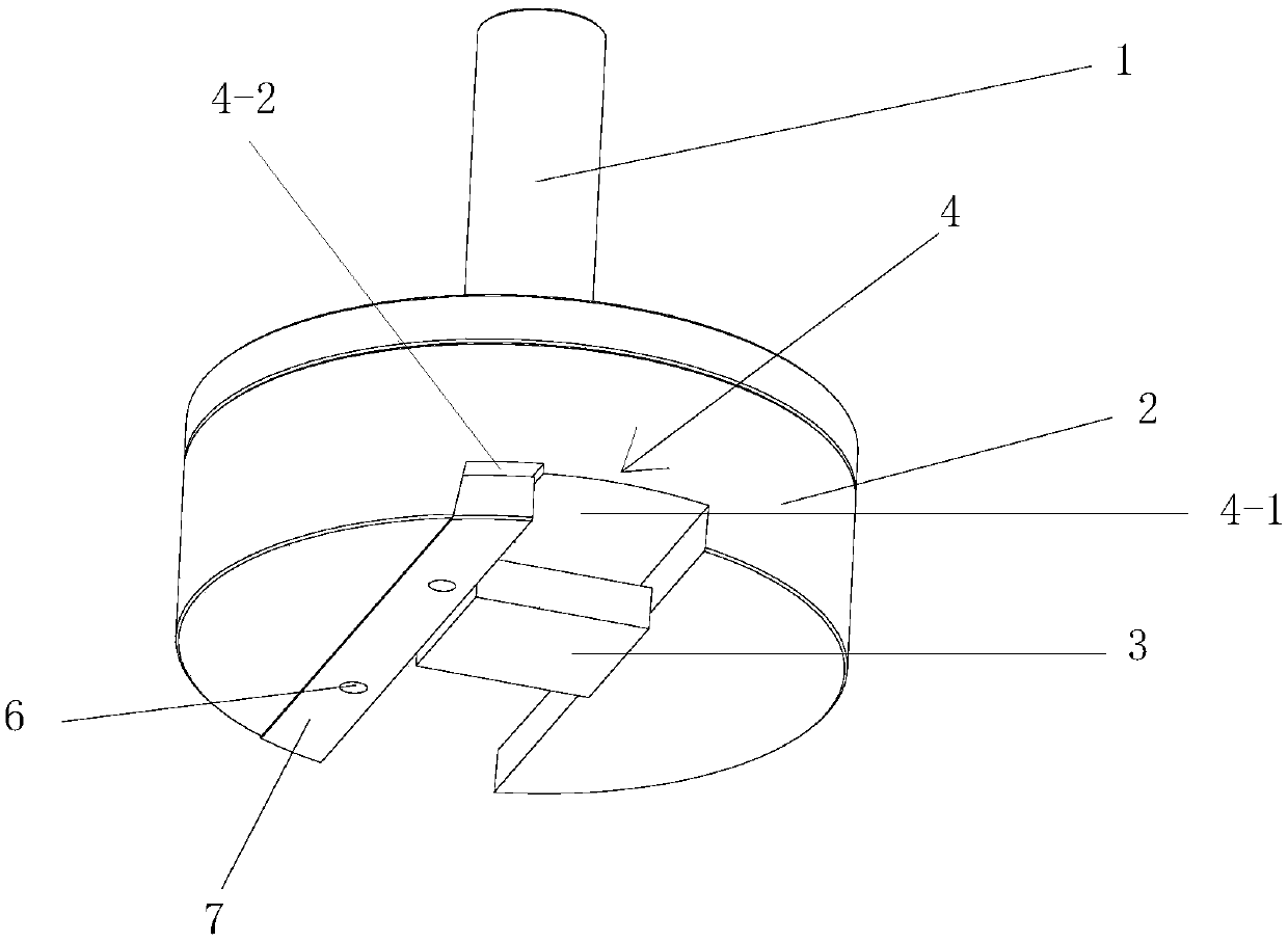
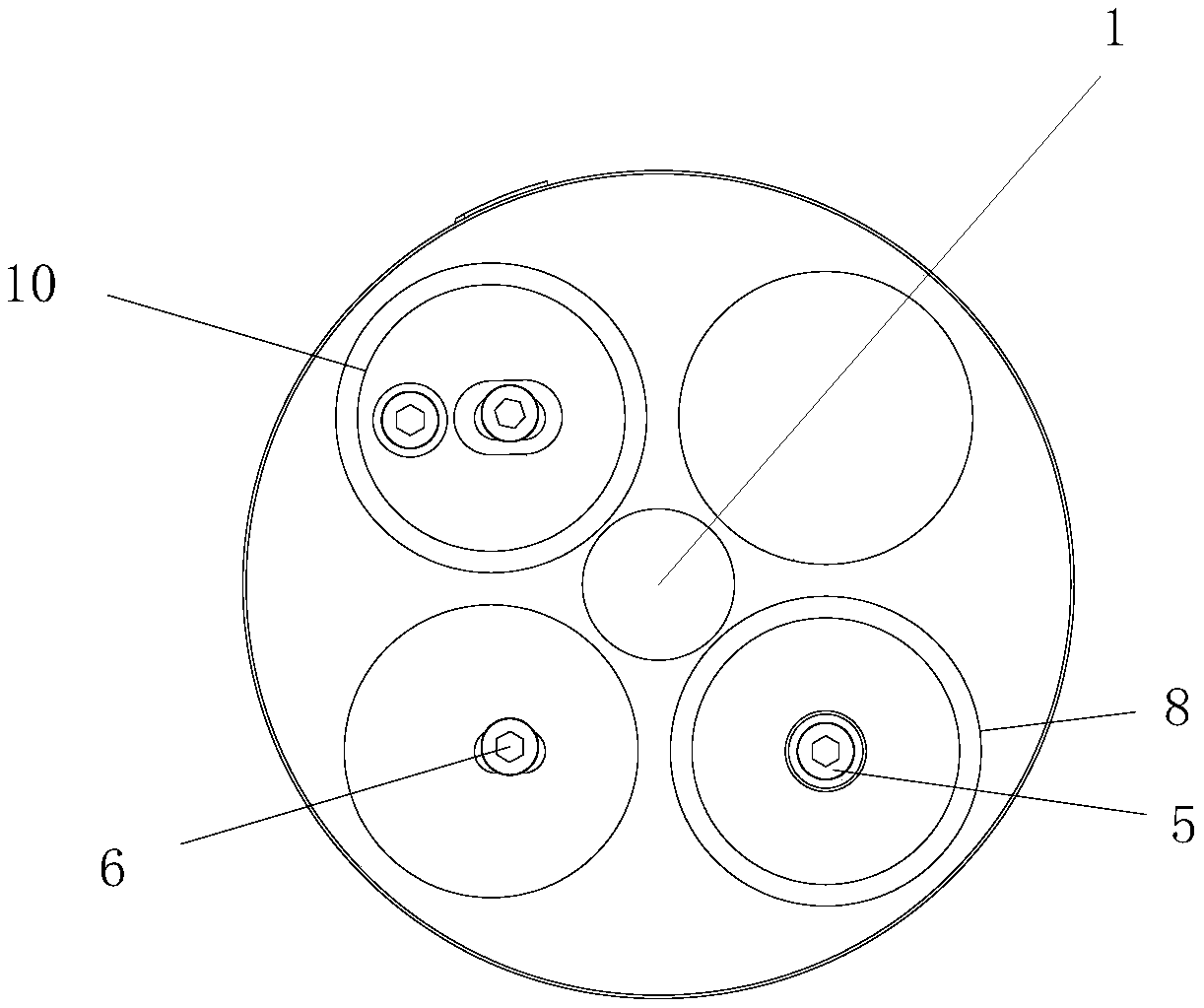
[0040] The present invention comprises a bottom mold 2, a connection mechanism installed on the bottom mold 2 and connected with the indenter 1 of the metallographic sample automatic grinding and polishing machine, and a metallographic sample 3 arranged on the bottom surface of the bottom mold 2 and used for installing the metallographic sample 3 Clamp mechanism, the connection mechanism is detachably connected with the bottom mold 2, the number of the connection mechanism is at least two, the structure and size of the two connection mechanisms are the same, each of the connection mechanisms includes a The upper side of the bottom mold 2 is matched with the boss 8 for installing the pressure head 1 and the positioning pin 5 for fixedly connecting the boss 8 with the bottom mold 2. The boss 8 is a stepped cylindrical boss, and the step The cylindrical boss includes a large cylindrical boss and a small cylindrical boss that is installed under the large cylindrical boss and integr...
Embodiment 2
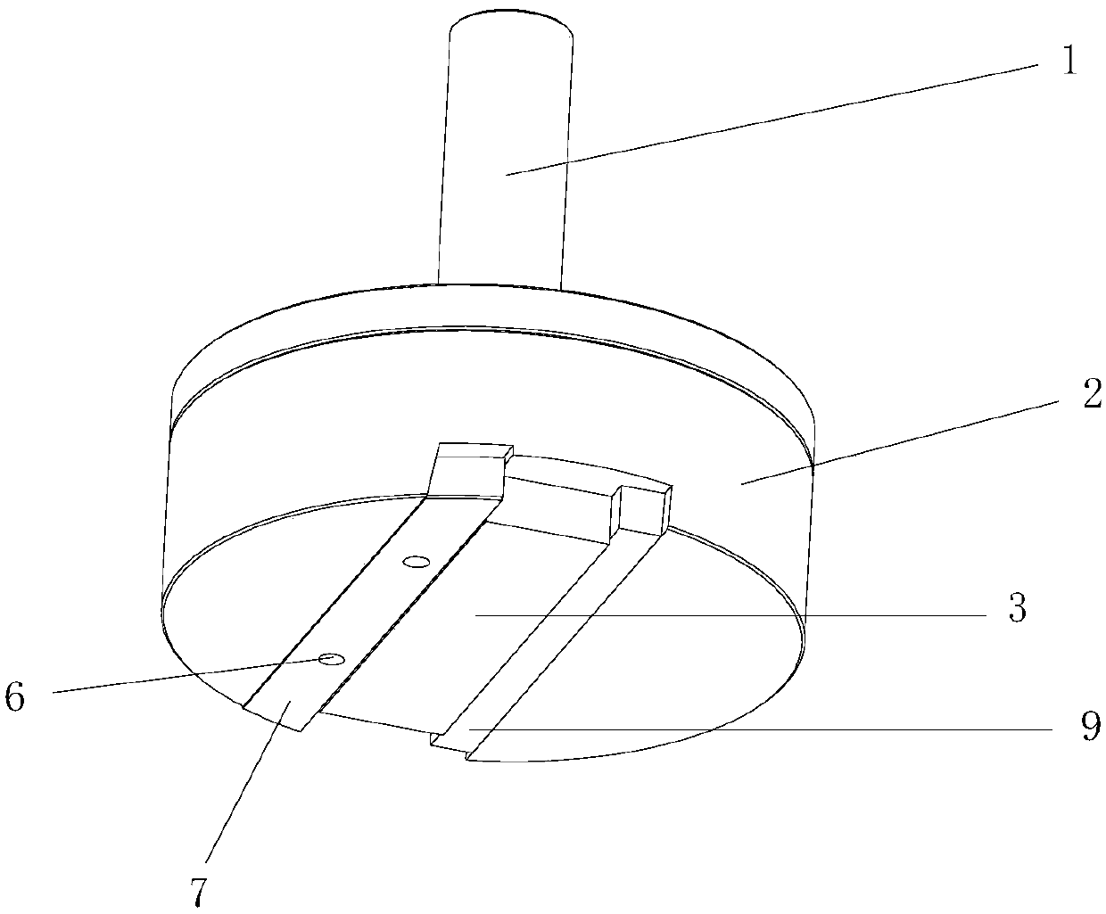
[0057] In this example, if image 3 As shown, the difference from Embodiment 1 is that the clamp mechanism also includes a second adjustment block 9 installed in the first groove 4-1, the second adjustment block 9 is a wedge block, and the first adjustment block The width of 7 gradually decreases from top to bottom, the side of the second adjustment block 9 close to the other side wall of the installation groove 4 is a slope, and the side of the second adjustment block 9 away from the other side wall of the installation groove 4 is vertical plane.
[0058] In this embodiment, the metallographic sample 3 is installed between the vertical surface of the first adjustment block 7 and the vertical surface of the second adjustment block 9 .
[0059] In this embodiment, by setting the second adjustment block 9 and installing it in the second groove 4-2, the metallographic sample 3 is sandwiched between the vertical surface of the first adjustment block 7 and the vertical surface of ...
Embodiment 3
[0065] In this example, if Figure 4 and Figure 5 As shown, the difference from Embodiment 2 is that the clamp mechanism also includes a second adjustment block 9 installed in the first groove 4-1, the second adjustment block 9 is an L-shaped adjustment block, and the L The shape adjustment block includes a horizontal part 9-1 and a vertical part 9-2 integrally formed with the horizontal part 9-1 and vertically arranged, and the width of the vertical part 9-2 gradually decreases from top to bottom, so The side of the vertical portion 9 - 2 close to the other side wall of the installation groove 4 is a slope, and the side of the vertical portion 9 - 2 away from the other side wall of the installation groove 4 is a vertical surface.
[0066] In this embodiment, the metallographic sample 3 is a rectangular thin plate sample, and the thickness of the rectangular thin plate sample is only about 2 mm. Therefore, by setting the vertical part 9-2 of the second adjustment block 9 and...
PUM
| Property | Measurement | Unit |
|---|---|---|
| diameter | aaaaa | aaaaa |
| thickness | aaaaa | aaaaa |
Abstract
Description
Claims
Application Information
 - R&D
- Intellectual Property
- Life Sciences
- Materials
- Tech Scout
- Unparalleled Data Quality
- Higher Quality Content
- 60% Fewer Hallucinations
Browse by: Latest US Patents, China's latest patents, Technical Efficacy Thesaurus, Application Domain, Technology Topic, Popular Technical Reports.
© 2025 PatSnap. All rights reserved.Legal|Privacy policy|Modern Slavery Act Transparency Statement|Sitemap|About US| Contact US: help@patsnap.com


