In-place detection method and device of airbag outline

A detection method and airbag technology, applied in the direction of surface polishing machine tools, parts of grinding machine tools, metal processing equipment, etc., can solve problems such as limited and not reaching the level of engineering application, to ensure consistency and improve removal effect , Improve the effect of stability and process controllability

Active Publication Date: 2017-05-31
LASER FUSION RES CENT CHINA ACAD OF ENG PHYSICS
View PDF6 Cites 6 Cited by
  • Summary
  • Abstract
  • Description
  • Claims
  • Application Information

AI Technical Summary

Problems solved by technology

However, although some achievements have been made in the development of airbag polishing equipment in China, it has not yet reached the level of engineering application. At the same time, the airbag polishing process is also limited by airbag polishing hardware, such as airbag tools.

Method used


Image

  • In-place detection method and device of airbag outline
  • In-place detection method and device of airbag outline
  • In-place detection method and device of airbag outline

Examples


Embodiment approach

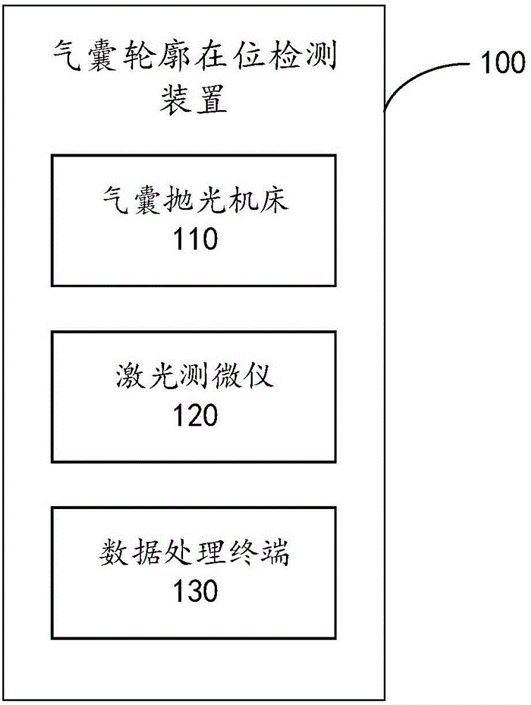
[0024] As an implementation manner, the airbag polishing machine tool 110 may be a 6-axis CNC machine tool, wherein the H axis is the rotation axis.

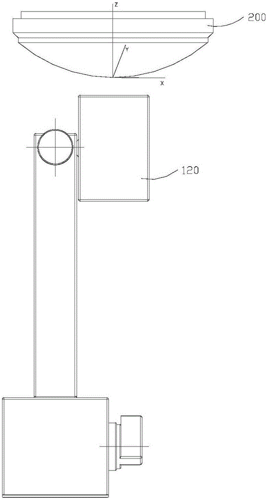
[0025] As an implementation manner, the laser micrometer 120 may be a Keyence laser micrometer 120 .

[0026] As an implementation manner, the data processing terminal 130 may be a computer.

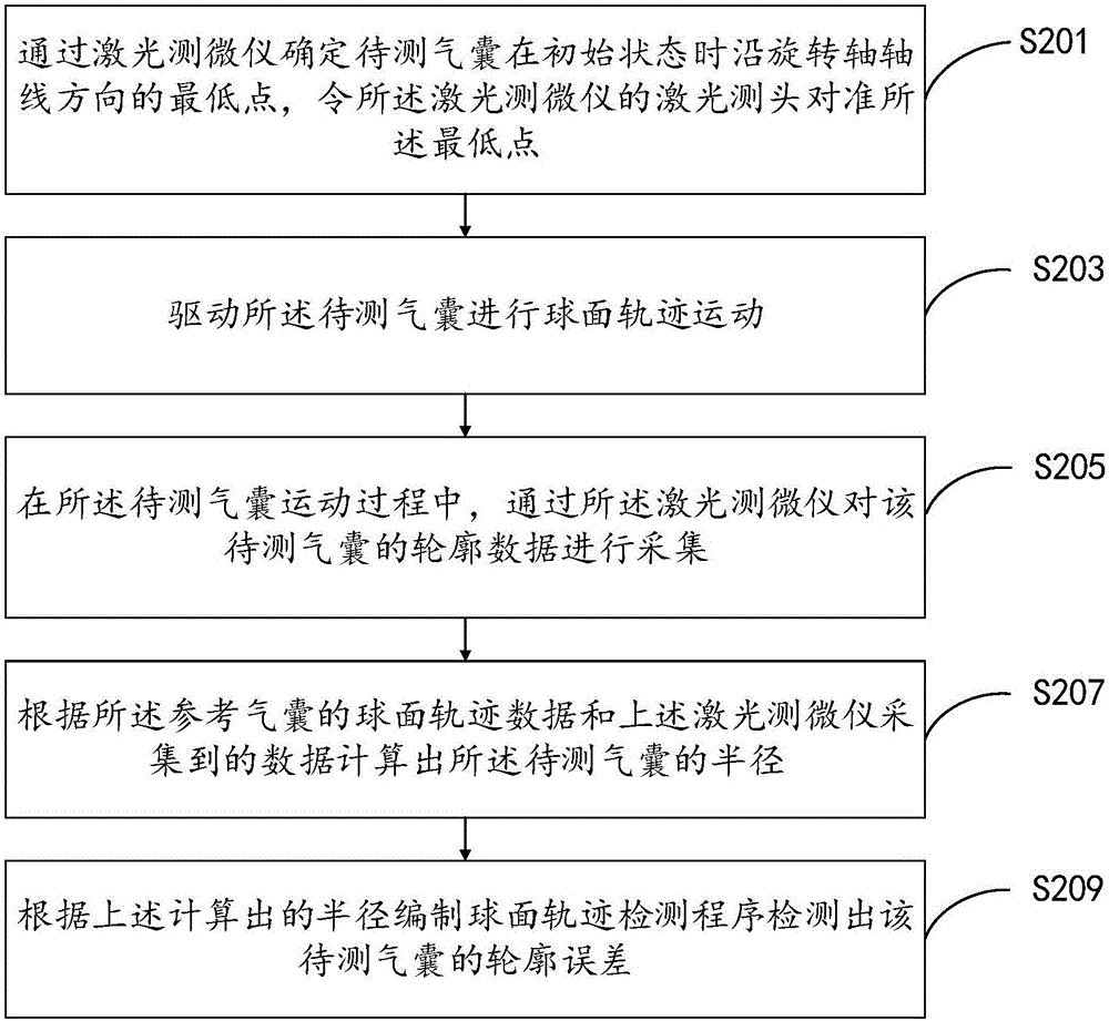
[0027] see figure 2 , is a method provided by the embodiment of the present invention that can be applied to figure 1 The flow chart of the detection method of the airbag contour in place of the device shown. It should be noted that the method in this example does not figure 2 and the specific order described below is a limitation. next to figure 2 Each step shown in is explained in detail.

[0028] Step S201 , determine the lowest point of the airbag 200 to be tested along the axis of the rotation axis in the initial state by the laser micrometer 120 , and align the laser measuring head of the laser micrometer 120 to the lowest p...


PUM


Abstract

The embodiment of the invention provides an in-place detection method and an in-place detection device of an airbag outline. Outline characteristics of an airbag to be detected are detected through an airbag polishing machine tool, a laser micrometer and calculation equipment for carrying out data processing, so that whether the airbag to be detected meets actual utilization requirements or not is judged. Compared with the prior art, the method and the device, provided by the embodiment of the invention, can effectively guarantee the consistency of the quality of the airbag outline and the stability and process controllability of airbag polishing removal are improved; and an actual removing function can be inferred based on the detected airbag outline characteristics, so that polishing process parameters are adjusted and the removing effect of an optical element is improved.

Description

technical field [0001] The invention relates to the field of advanced optical manufacturing technology, in particular to a method and device for detecting the presence of an airbag outline. Background technique [0002] With the continuous development of modern science and technology, especially the rapid advancement of cutting-edge science and technology such as aerospace, national defense, information, microelectronics and optoelectronics, higher and higher requirements are placed on the field of optical processing. Among them, the large-aperture aspheric element has the advantages of no central obstruction, improved image quality, and simplified system structure. It has become the key element of space cameras, extreme ultraviolet lithography machines, and ultra-high-power laser devices. Its ultra-precision processing is an important aspect in the field of optical processing. One of the cutting-edge research directions. [0003] Airbag polishing is one of the research hot...

Claims


Application Information

Patent Timeline
Patent Type & Authority Applications(China)
IPC IPC(8): B24B49/12B24B29/00
CPCB24B29/00B24B49/12
Inventor 钟波陈贤华文中江王健许乔侯晶徐曦郑楠
Owner LASER FUSION RES CENT CHINA ACAD OF ENG PHYSICS
Why Eureka
Try Eureka