Variable-rigidity mechanism based on geometrical features

A technology with geometric characteristics and variable stiffness, applied in the field of robotics, can solve the problems of complex structure, poor linearity, and low position accuracy of variable stiffness mechanisms, and achieve the effects of good linearity, improved control accuracy, and convenient layout.

Active Publication Date: 2017-05-31
HARBIN INST OF TECH
View PDF6 Cites 9 Cited by
  • Summary
  • Abstract
  • Description
  • Claims
  • Application Information

AI Technical Summary

Problems solved by technology

[0004] The present invention aims to solve the problems of complex structure and poor linearity of existing variable stiffness mechanisms, as well as the existence of gaps and friction between rods when using fulcrum movement, resulting in low position accuracy, and further provides a variable stiffness mechanism based on geometric characteristics

Method used


Image

  • Variable-rigidity mechanism based on geometrical features
  • Variable-rigidity mechanism based on geometrical features
  • Variable-rigidity mechanism based on geometrical features

Examples


Embodiment Construction

[0018] The technical solutions of the present invention will be further described below in conjunction with the accompanying drawings and through specific implementation methods.

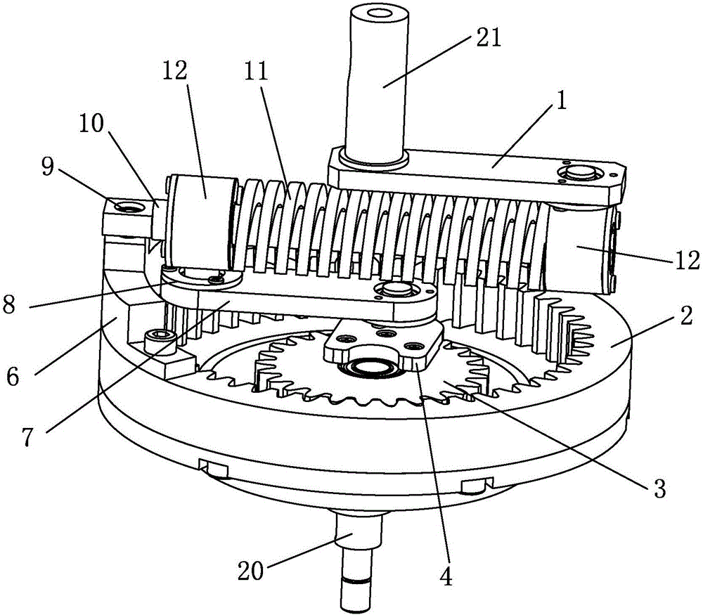
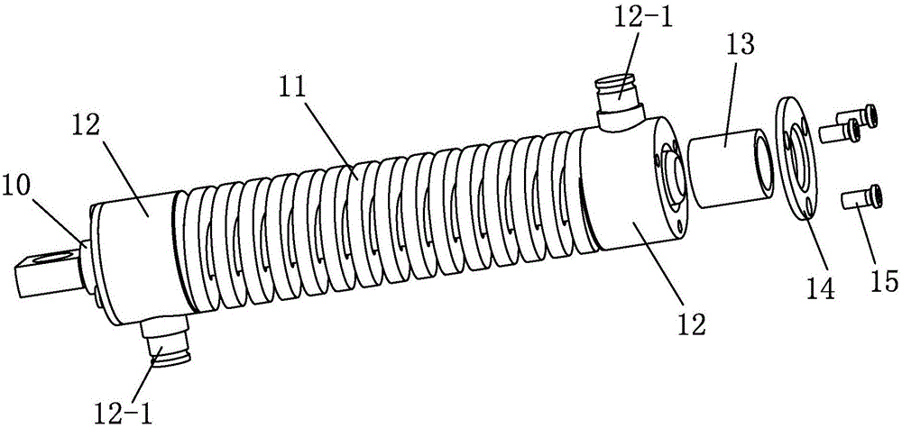
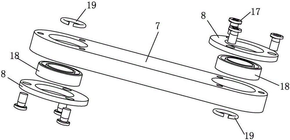
[0019] combine Figure 1-Figure 3 Explain that a variable stiffness mechanism based on geometric characteristics in this embodiment includes an output rod 1, a rigidly adjustable ring gear 2, a fulcrum gear 3, a fulcrum frame 4, a fulcrum rod 7, an intermediate rod 10, a spring 11, a bushing 13 and two sliders 12;

[0020] The two ends of described intermediate bar 10 are respectively equipped with a described slide block 12, and the described intermediate bar 10 that is positioned between two described slide blocks 12 is provided with spring 11, and is set between slide block 12 and intermediate bar 10. There is a shaft sleeve 13, and the shaft sleeve 13 is axially positioned by the bearing end cover 14 installed on the slider 12;

[0021] The upper end of the rigidly adjustable main shaft 20 is ...


PUM


Abstract

The invention relates to a joint variable-rigidity mechanism, in particular to a variable-rigidity mechanism based on geometrical features. The variable-rigidity mechanism aims to solve the problems that an existing variable-rigidity mechanism is complex in structure and poor in linearity, gaps and friction exist between the mechanism and a rod when the mechanism moves through a fulcrum, and consequently the position precision is low. The variable-rigidity mechanism comprises an output rod, a rigidity adjusting inner gear ring, a fulcrum gear, a fulcrum frame, a fulcrum bar, a middle rod, a spring, a shaft sleeve and two sliding blocks, wherein the sliding blocks are arranged at the two ends of the middle rod correspondingly, the spring is arranged on the middle rod located between the two sliding blocks in a sleeving mode, the shaft sleeve is arranged between the sliding blocks and the middle rod in a sleeving mode, and the shaft sleeve is axially positioned through bearing end covers arranged on the sliding blocks; and the fulcrum gear is engaged with the rigidity adjusting inner gear ring, and the fulcrum gear is arranged below the fulcrum frame and detachably connected with the fulcrum frame. The variable-rigidity mechanism is applied to a robot elbow joint.

Description

technical field [0001] The invention relates to a joint variable stiffness mechanism, in particular to a geometric characteristic-based variable stiffness mechanism for a robot joint, and belongs to the technical field of robots. Background technique [0002] Since the 21st century, humans and robots have come into contact with each other more frequently in various environments, and the safety issues of human-computer interaction have gradually entered the human field of vision. In particular, the frequent incidents of machine injuries caused by traditional rigid robots have also constantly reminded people of human-machine collaboration. The importance of environmental safety. Although flexible joints solve the problem of safety, their influence on system response and control accuracy has led researchers to explore more advanced flexible joints. One of the important directions is variable stiffness flexible joints. Variable stiffness flexible joints are a new type of flexib...

Claims


Application Information

Patent Timeline
Patent Type & Authority Applications(China)
IPC IPC(8): B25J17/00B25J19/00
CPCB25J17/00B25J19/00
Inventor 刘玉斌张赫蔡若凡李戈赵杰
Owner HARBIN INST OF TECH
Why Eureka
Try Eureka