Flow-casting production equipment for zirconium oxide substrates

A zirconia-based, production equipment technology, applied in the field of zirconia substrate casting production equipment, can solve the problems of bending cracking, easy generation of surface stripes, and stripes on the surface of the green sheet, etc., to achieve outstanding substantive features, high efficiency and high quality Production, uniform thickness effect

Pending Publication Date: 2017-05-31
陈振宁
View PDF9 Cites 0 Cited by
  • Summary
  • Abstract
  • Description
  • Claims
  • Application Information

AI Technical Summary

Problems solved by technology

In the prior art, zirconia substrates are produced by tape casting. In the casting stage of tape casting production, a flat scraper with a single blade is usually used to scrape the surface of the slurry to form a billet. It is difficult to control the viscosity and rheological properties, so the surface of the green sheet is prone to surface streaks during the casting stage; in addition, when the stock tank is continuously fed through multiple feeding pipes, the slurry will also cause Because the slurry cannot be kept uniform during the moving process and tends to be short-range ordered, resulting in streaks on the surface of the green sheet; also, in the drying stage of tape casting production, the drying process of the green sheet in the drying chamber usually adopts the method of blowing hot air , the way of

Method used


Image

  • Flow-casting production equipment for zirconium oxide substrates
  • Flow-casting production equipment for zirconium oxide substrates
  • Flow-casting production equipment for zirconium oxide substrates

Examples


Embodiment Construction

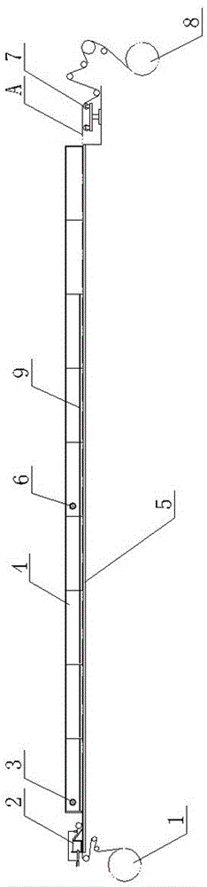
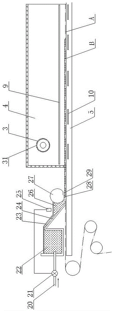
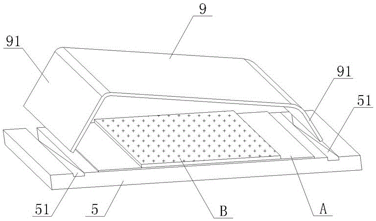
[0017] As shown in the figure, the tape casting production equipment of zirconia substrate of the present invention comprises working platform 5, unwinding mechanism 1 and winding mechanism 8 that are located at the front and rear ends of working platform 5, and the surface of working platform 5 is paved with stainless steel plate material. Casting carrier plate, the film belt A unrolled by the unwinding mechanism 1 is rewound by the rewinding mechanism 8 after passing through the surface of the working platform 5 horizontally. 5. A casting device 2 is provided at one end close to the unwinding mechanism 1, and nine drying chambers 4 are arranged above the working platform 5 along the front and rear directions. The nine drying chambers communicate with each other and form a closed drying space above the working platform 5. In the enclosed drying space, a first exhaust pipe 3 is provided at the front end (inlet side of the first drying chamber), and a second exhaust pipe 6 is ar...


PUM


Abstract

The invention discloses flow-casting production equipment for zirconium oxide substrates. The flow-casting production equipment is characterized in that a flow-casting bearing plate made of a stainless steel plate material is laid on the surface of a working platform, a film band paid off by a pay-off mechanism is taken up by a take-up mechanism after passing through the surface of the working platfrom, a flow-casting device is arranged at the end, close to the pay-off mechanism, of the working platform, a plurality of drying chambers are arranged on the working platform, the multiple drying chambers communicate with one another, a closed drying space is formed on the working platform, a first exhaust pipe is arranged at the front end in the closed drying space, a second exhaust pipe is arranged in the middle position in the closed drying space, glass baffles are arranged in the drying chambers and shield the film band passing through the drying chambers, the glass baffles are horizontally arranged in an inclined mode in the transverse direction, and a resistance wire heater with a thermocouple is installed at the bottom of the flow-casting bearing plate. According to the flow-casting production equipment, efficient high-quality production of the zirconium oxide substrates can be achieved, and the produced zirconium oxide substrates are free of cracking, flat in surface and even in thickness.

Description

technical field [0001] The invention relates to the technical field of zirconia sensors, in particular to zirconia substrate casting production equipment for making zirconia sensor chips. Background technique [0002] Zirconia sensor is used to measure the amount of residual oxygen in the combustion process of automobiles, which plays an active role in reducing environmental pollution and improving combustion efficiency. The key component of the zirconia sensor is the zirconia chip, and the latest zirconia chip adopts the lamination process of multi-layer zirconia substrates. In the prior art, zirconia substrates are produced by tape casting. In the casting stage of tape casting production, a flat scraper with a single blade is usually used to scrape the surface of the slurry to form a billet. It is difficult to control the viscosity and rheological properties, so the surface of the green sheet is prone to surface streaks during the casting stage; in addition, when the stoc...

Claims


Application Information

Patent Timeline
IPC IPC(8): B28B1/29B28B1/30B28B5/02B28B11/24
CPCB28B1/29B28B1/30B28B5/027B28B11/243
Inventor 陈振宁
Owner 陈振宁
Why Eureka
Try Eureka