
High temperature deep well goaf filling slurry conveying system and method with cooling function

A technology for filling slurry and conveying system, which is applied in chemical instruments and methods, batching storage, batching batching instrument, etc. High-level, simple method and steps

Active Publication Date: 2017-09-29
XIAN UNIV OF SCI & TECH
View PDF4 Cites 0 Cited by
  • Summary
  • Abstract
  • Description
  • Claims
  • Application Information

AI Technical Summary

Problems solved by technology

The cold source (ice flakes or cold water, etc.) is produced by the refrigeration station, and is transported to the air cooler of the mining face through the special cold port frozen water pipe, and exchanges heat with the hot and humid air on the working face, thereby reducing the ambient temperature and humidity of the working face. The cooling water after the heat exchange will condense the heat out of the working surface (such as the ground, etc.); the cooling system has many disadvantages: the system is complex, the total installed power is large, and the energy consumption is high; the cooling pipeline is long, and the cooling capacity loss of the system is large. The fluidized ice production process needs to add salt, which has a corrosive effect on the cooling pipeline and equipment; it is necessary to install a large-diameter cooling pipeline in the wellbore and insulate the pipeline; the ground refrigeration workshop occupies a large area, etc.
[0004] The two major problems that deep mine mining will face in the future are empty space filling and mine cooling. At present, the paste filling technology is not perfect, and there are many problems in the slurry transportation, and it is difficult to form a stable structural flow; the mine cooling system is complicated. , high operating cost, low cooling efficiency

Method used


Image

  • High temperature deep well goaf filling slurry conveying system and method with cooling function
  • High temperature deep well goaf filling slurry conveying system and method with cooling function
  • High temperature deep well goaf filling slurry conveying system and method with cooling function

Examples


Embodiment Construction

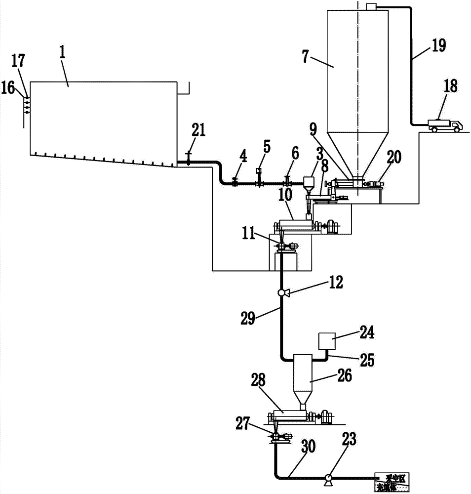
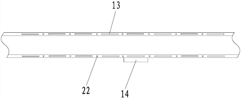
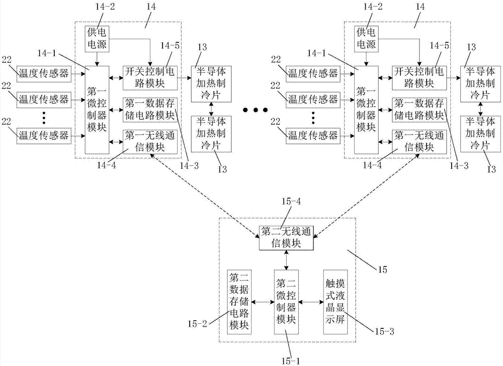
[0050] Such as figure 1 As shown, the high-temperature deep well goaf filling slurry conveying system with cooling function of the present invention includes an above-hole material conveying mechanism and an underground material conveying mechanism, and the above-hole material conveying mechanism includes a first material conveying mechanism and a second material conveying mechanism , the mixing mechanism on the well and the temperature master controller 15, the first material conveying mechanism includes a first material bin 1 for holding the first material, a hopper for transporting the first material mixed with ice cubes to the mixing mechanism 3 and the first material conveying pipeline 2 connected to the material outlet of the first material bin 1, the first material conveying pipeline 2 is connected with a material conveying switch valve 21, an electromagnetic flowmeter 4, an electric pinch valve 5 and a manual A pinch valve 6, the hopper 3 is connected to the end of the...


PUM


Abstract

The invention discloses a high-temperature deep well goaf filling slurry conveying system with a cooling function, which comprises an uphole material conveying mechanism and an underground material conveying mechanism. The abovewell material conveying mechanism includes a first material conveying mechanism, a second material conveying mechanism, The mixing mechanism and the temperature master controller, the first material conveying mechanism includes the first material bin, the hopper and the first material conveying pipeline, the second material conveying mechanism includes the second material bin and the second material conveying pipeline, and the above-ground mixing mechanism includes the first A twin-shaft mixer and a first high-speed mixer, the conveying mechanism includes an underground mixing mechanism, an ice maker, and an ice particle delivery pipe connected to the ice maker, and the underground mixing mechanism includes a material mixing bin, a second twin-shaft mixer and a second high-speed mixer; The invention also discloses a high-temperature deep well goaf filling slurry conveying method with the function of cooling. The invention has the advantages of convenient use and operation, high working reliability, strong practicability, good use effect and convenient popularization and use.

Description

technical field [0001] The invention belongs to the technical field of goaf filling in high-temperature deep wells, and in particular relates to a high-temperature deep well goaf filling slurry delivery system and method with a cooling function. Background technique [0002] With the gradual reduction and depletion of shallow resources, the depth of mining is increasing. At present, mines facing deep mining in China account for 90% of the total number of mines in the country; deep mining faces many problems such as high ground stress, high ground temperature, and high osmotic pressure. Increased difficulty, deteriorating operating environment, drastic increase in ventilation and cooling, and production costs have posed severe challenges to the mining of deep resources; in order to achieve safe production, the application of filling technology is essential in the development of deep resources. Waste materials are backfilled underground to treat empty areas, thereby greatly im...

Claims


Application Information

Patent Timeline
Patent Type & Authority Patents(China)
IPC IPC(8): B28C5/00B28C5/08B28C7/00B28C7/04B28C7/06B28C7/12B28C9/00
CPCB28C5/006B28C5/08B28C7/0053B28C7/0404B28C7/06B28C7/12B28C9/00
Inventor 刘浪张小艳孙伟博邱华富王燕张波王美
Owner XIAN UNIV OF SCI & TECH
Learn More