Building lifting device

A lifting device and construction technology, applied in hoisting devices, cranes, clockwork mechanisms, etc., can solve the problems of manual lifting, affecting the construction progress, inconvenient installation, etc., achieve flexible lifting, improve construction efficiency, and facilitate The effect of mobile use

Inactive Publication Date: 2017-05-31
刘畅
View PDF0 Cites 0 Cited by
  • Summary
  • Abstract
  • Description
  • Claims
  • Application Information

AI Technical Summary

Problems solved by technology

[0002] Now, in the construction industry, when building a building, tower cranes or rolling machines are used to hoist floors or bricks and mud, but these equipment are not suitable for civil buildings. At present, small buildings in rural and townships, especially private households Building a house, due to the limitations of various factors such as the structure of the house, the topography of the house, and economic conditions, most of them are lifted or hoisted by manpower. The floor is installed on the roof, which requires manpower to lift and install, which is not only laborious and time-consuming, but also extremely unsafe. It is because the work site is small and cannot be installed; the power source is difficult to solve and the cost is high
[0003] The current hoisting device has a large machine base, the equipment is huge and complicated, it is inconvenient to install, it is inconvenient to move and use on different construction sites, and when in use, the rotation, lifting and lifting are not flexible, which affects the construction progress

Method used


Image

  • Building lifting device
  • Building lifting device

Examples


Embodiment Construction

[0017] In order to more clearly illustrate the technical solutions in the embodiments of the present invention or the prior art, the following will briefly introduce the drawings that need to be used in the description of the embodiments or the prior art. Obviously, the accompanying drawings in the following description are only These are some embodiments of the present invention. For those skilled in the art, other drawings can also be obtained according to these drawings without any creative effort.

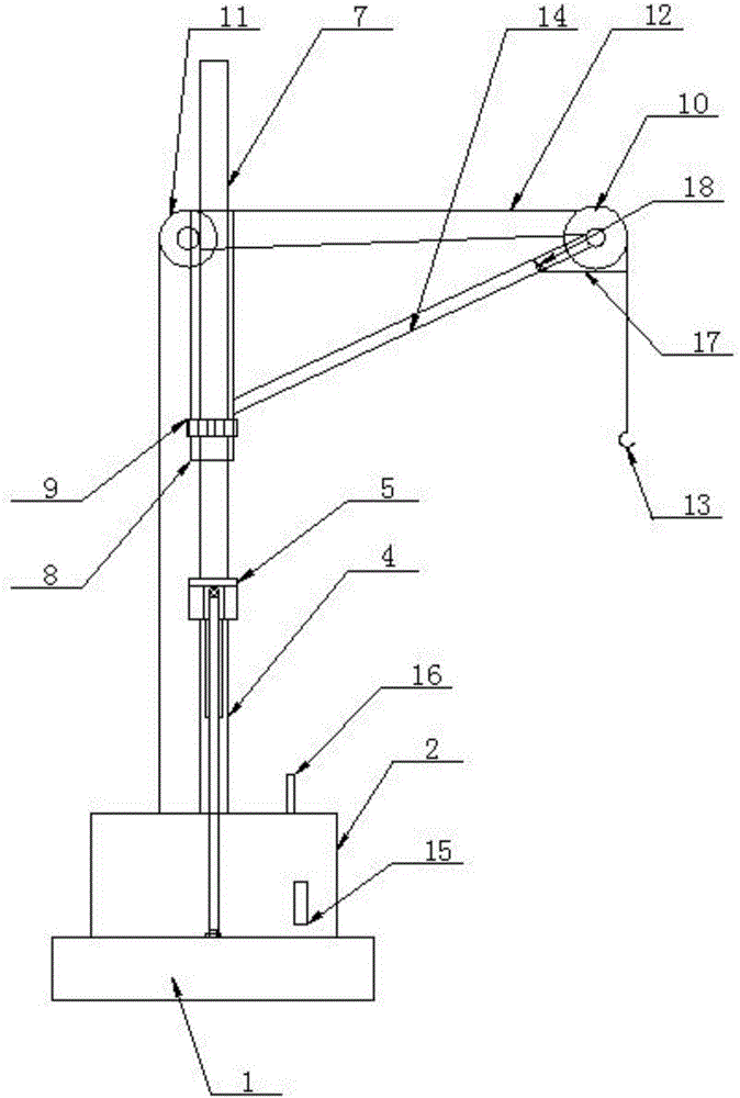
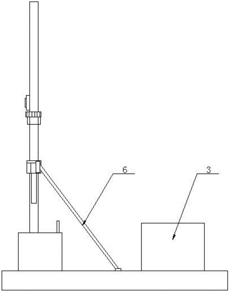
[0018] see as figure 1 —— figure 2 As shown, this specific embodiment adopts the following technical scheme: it includes a base plate 1, a power unit 2, a counterweight 3, a column 4, a sleeve 5, a diagonal bar 6, a turret 7, a bearing 8, a clamp 9, a A pulley 10, a second pulley 11, a wire rope 12, a suspension hook 13, and a lifting arm 14; the base plate 1 is provided with a power unit 2 and a counterweight 3, and the power unit 2 is connected with a column 4, and the colu...


PUM


Abstract

The invention discloses a building lifting device relating to the technical field of building construction equipment. The building lifting device comprises a bottom plate, a power device, a counterweight, a stand column, a sleeve, a sway rod, a rotary rack, a bearing, a clamping device, a first pulley, a second pulley, a steel wire rope, a lifting hook and a lifting arm. The power device and the counterweight are arranged on the bottom plate, the power device is connected to the stand column, the sleeve is formed in the stand column, and one end of the sway rod is fixedly connected to the sleeve while the other end of the sway rod is fixedly connected to the bottom plate; the upper end of the stand column is connected to the rotary rack through the bearing and the clamping device, the rotary rack is hinged to the lifting arm, one end of the lifting arm is connected to the second pulley, the first pulley is arranged on the rotary rack, and the steel wire is successively connected to the power device, the second pulley, the first pulley and the lifting hook. The building lifting device disclosed by the invention is relatively small in size, convenient to move by a mobile vehicle and flexible to rotate and lift, and the construction efficiency is increased.

Description

technical field [0001] The invention relates to the technical field of building construction equipment, in particular to a building lifting device. Background technique [0002] Now, in the construction industry, tower cranes or roll machines are used to hoist floors or bricks and mud when building buildings, but these equipment are not suitable for civil buildings. At present, small buildings in rural and townships, especially private households Building a house, due to the limitations of various factors such as the structure of the house, the topography of the house, and economic conditions, etc., most of them are lifted or hoisted by manpower. The floor is installed on the roof, which requires manpower to lift and install. It is because the working site is small and cannot be installed; the power source is difficult to solve and the cost is high. [0003] The current hoisting device has a large machine base, the equipment is huge and complicated, it is inconvenient to in...

Claims


Application Information

Patent Timeline
IPC IPC(8): B66C23/72B66C23/64B66D1/14
CPCB66C23/72B66C23/64B66D1/14
Inventor 刘畅吕海峰
Owner 刘畅
Why Eureka
Try Eureka