Slay direct connection type pneumatic trimming device

A direct connection and sley technology, applied in the direction of textile, textile, papermaking, loom, etc., can solve the problems of inaccurate control, increased weaving cost, low efficiency, etc., to avoid radial force, prolong service life, The effect of improving convenience

Active Publication Date: 2017-05-31
QINGDAO TIANYI GROUP RED FLAG TEXTILE MACHINERY
View PDF7 Cites 6 Cited by
  • Summary
  • Abstract
  • Description
  • Claims
  • Application Information

AI Technical Summary

Problems solved by technology

[0003] At present, most of the smooth edge devices used in the market are reed-cut type smooth edge devices. When using this type of smooth edge device, it is necessary to cut the reed to meet the weaving requirements of different varieties when adjusting the weaving variety, but cutting the reed will cause waste of reed , increase weaving cost and reduce weft insertion efficiency
Moreover, most of the existing reed type smooth edge devices are mechanical smooth edge devices, which mainly have complex mechanical structures, high manufacturing costs, limited range of loom speeds (usually the main engine speed is 300-400rpm), low efficiency, and are particularly important. The most important thing is that the control of the weft yarn by the mechanical smoothing is very inaccurate. When weaving cotton and linen fabrics, the weft yarn is not easy to control, resulting in a high rate of outcropping and poor smoothing effect.
In addition, there are a small number of non-reed pneumatic or mechanical smooth edge devices on the market, but their speed is not high, the efficiency is low, there are many wearing parts, and the service life is short

Method used


Image

  • Slay direct connection type pneumatic trimming device
  • Slay direct connection type pneumatic trimming device
  • Slay direct connection type pneumatic trimming device

Examples


Embodiment 1

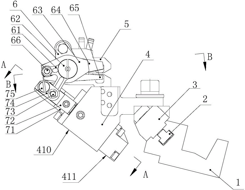
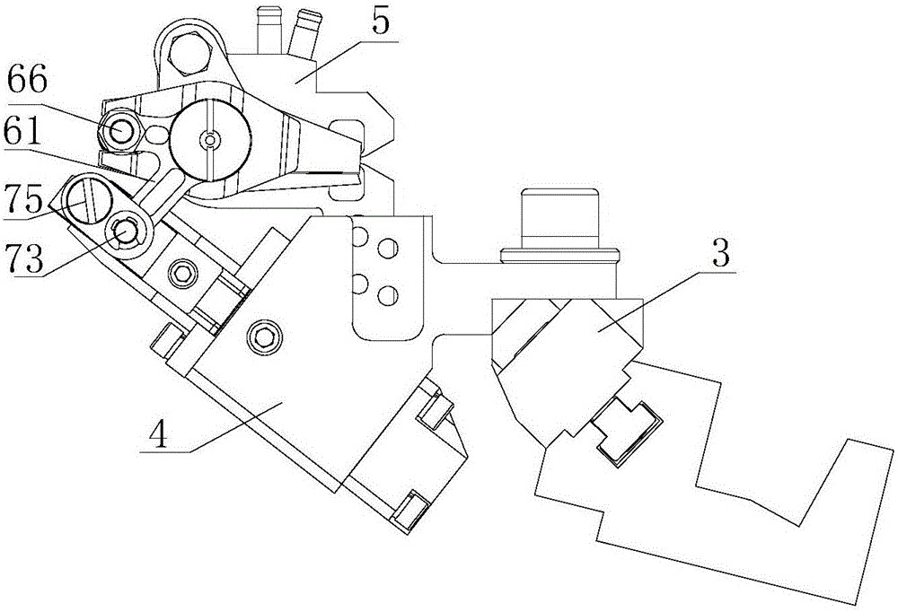
[0030] Such as Figure 1 to Figure 4 As shown, a sley direct-connected pneumatic smoothing device includes a beating sley 1, a cylinder 4, a pneumatic hemming device 5, and a weft scissors mechanism 6. The cylinder 4 is connected to the beating sley 1, and the pneumatic folding Side device 5 is installed on the cylinder 4, and weft yarn scissors mechanism 6 is arranged on the pneumatic hemming device 5, and described cylinder 4, pneumatic hemming device 5 and weft yarn scissors mechanism 6 swing together with beat-up sley 1.

[0031] The sley direct connection type pneumatic smoothing device also includes a cylinder positioning seat 3, the cylinder 4 is installed on the cylinder positioning seat 3, the cylinder positioning seat 3 is installed on the beating sley 1, and the cylinder 4 is mounted on the cylinder positioning seat 3. The installation position on the cylinder is adjustable, and the cylinder positioning seat 3 is provided with a long hole 9 for installing the cylind...

Embodiment 2

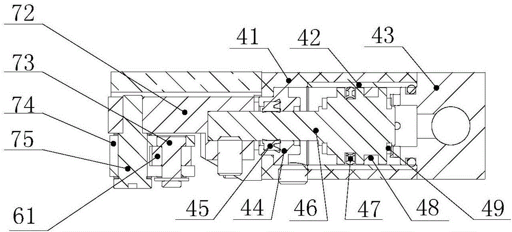
[0040] Such as Figure 5 As shown, the structure and principle of this embodiment and Embodiment 1 are basically the same, the only difference lies in the structural composition of the scissors driving mechanism, the scissors driving mechanism in this embodiment includes a second guide seat 81, a second driving slider 82 and the third pin shaft 83, the second guide seat 81 is connected with the cylinder 4, the second drive slider 82 is connected with the piston rod 46 of the cylinder 4, and the second guide seat 81 is provided with a Adapted second guide groove, the second drive slider 82 is driven by the piston rod 46 to do linear reciprocating motion along the second guide groove; the scissors driving mechanism also includes a roller 84, and the second drive slider 82 is provided with The third guide groove that is compatible with the roller 84, the roller 84 is hinged with the scissors rocker arm 61 through the third pin shaft 83, when the second drive slider 82 does recipr...

Embodiment 3

[0042] The structure and principle of this embodiment and the second embodiment are basically the same, the only difference is: the roller 84 is replaced by the third driving slider, at this time, the third guide groove is matched with the third driving slider, and the third driving slider The three driving sliders are hinged with the scissors rocker arm 61 through the third pin shaft 83. When the second driving slider 82 is doing reciprocating linear motion, when the side wall of the third guide groove touches the third driving slider, it will drive the third driving slider. The three drive sliders slide, thereby driving the rocker arm 61 of the scissors to swing, and driving the moving piece of the scissors 64 to rotate around the eccentric pin shaft 66, so as to realize the opening and closing of the moving and static pieces of the scissors.

[0043] The working principles of the second embodiment and the third embodiment are roughly: when the beating sley 1 of the loom swin...


PUM


Abstract

The invention discloses a slay direct connection type pneumatic trimming device. The slay direct connection type pneumatic trimming device includes a weft beating-up slay, an air cylinder, a pneumatic hemmer, and a weft yarn scissors mechanism; the air cylinder is connected to the weft beating-up slay; the pneumatic hemmer is arranged on the air cylinder; the weft yarn scissors mechanism is arranged on the pneumatic hemmer; and the air cylinder, the pneumatic hemmer, and the weft yarn scissors mechanism swing with the weft beating-up slay. The air cylinder, the weft yarn scissors mechanism, and the pneumatic hemmer are integrally arranged on an air cylinder positioning base to form a unit, the air cylinder positioning base is connected to a T-shaped groove of the weft beating-up slay, and then the air cylinder, the weft yarn scissors mechanism, and the pneumatic hemmer can swing with the weft beating-up slay; and the convenience of a weft beating-up operation is improved, abrasion is reduced, and the service life is prolonged.

Description

technical field [0001] The invention belongs to the technical field of looms, and in particular relates to a sley direct connection type pneumatic smoothing device. Background technique [0002] During the weaving process of the loom, the two ends of the weft yarn are usually cut by scissors, and the cut ends are exposed and not wrapped inside the fabric, so the exposed ends become burrs, and products with burrs, its The surface smoothness is low, resulting in poor body feeling for users. In order to solve the smooth edge problem in weaving, a smooth edge device has appeared. [0003] At present, most of the smooth edge devices used in the market are reed-cut type smooth edge devices. When using this type of smooth edge device, it is necessary to cut the reed to meet the weaving requirements of different varieties when adjusting the weaving variety, but cutting the reed will cause waste of reed , increase weaving cost and reduce weft insertion efficiency. Moreover, most o...

Claims


Application Information

Patent Timeline
Patent Type & Authority Applications(China)
IPC IPC(8): D03D47/48D03D47/36D03D49/60
CPCD03D47/36D03D47/48D03D49/60
Inventor 刘培德张树杰高玉刚纪竹青赵付斌
Owner QINGDAO TIANYI GROUP RED FLAG TEXTILE MACHINERY
Why Eureka
Try Eureka