
A movable anti-separation support

An anti-separation and moving body technology, applied in the direction of the engine base, supporting machine, pipeline bracket, etc., can solve the problems of being damaged by the supported body, unable to limit movement, unable to limit the amount of friction and slippage, etc., to improve stability and facilitate processing. Effect

Active Publication Date: 2019-08-13
税浩旭 +2
View PDF6 Cites 0 Cited by
  • Summary
  • Abstract
  • Description
  • Claims
  • Application Information

AI Technical Summary

Problems solved by technology

[0004] 1. Under the action of external force perpendicular to the direction of translation, it cannot be guaranteed that the upper and lower sliding surfaces of the support device will not be separated. Once separated, the supported body will face damage;
[0005] 2. Under the action of external force, the amount of frictional slip cannot be limited;
[0007] 4. Due to the separation phenomenon of friction sliding bearings during the vibration process, the stability of the sliding process cannot be guaranteed
[0008] There is also a rubber cushion shock absorber in the prior art, but it can only weaken the force of vibration and cannot restrict movement

Method used


Image

  • A movable anti-separation support
  • A movable anti-separation support
  • A movable anti-separation support

Examples


Embodiment 1

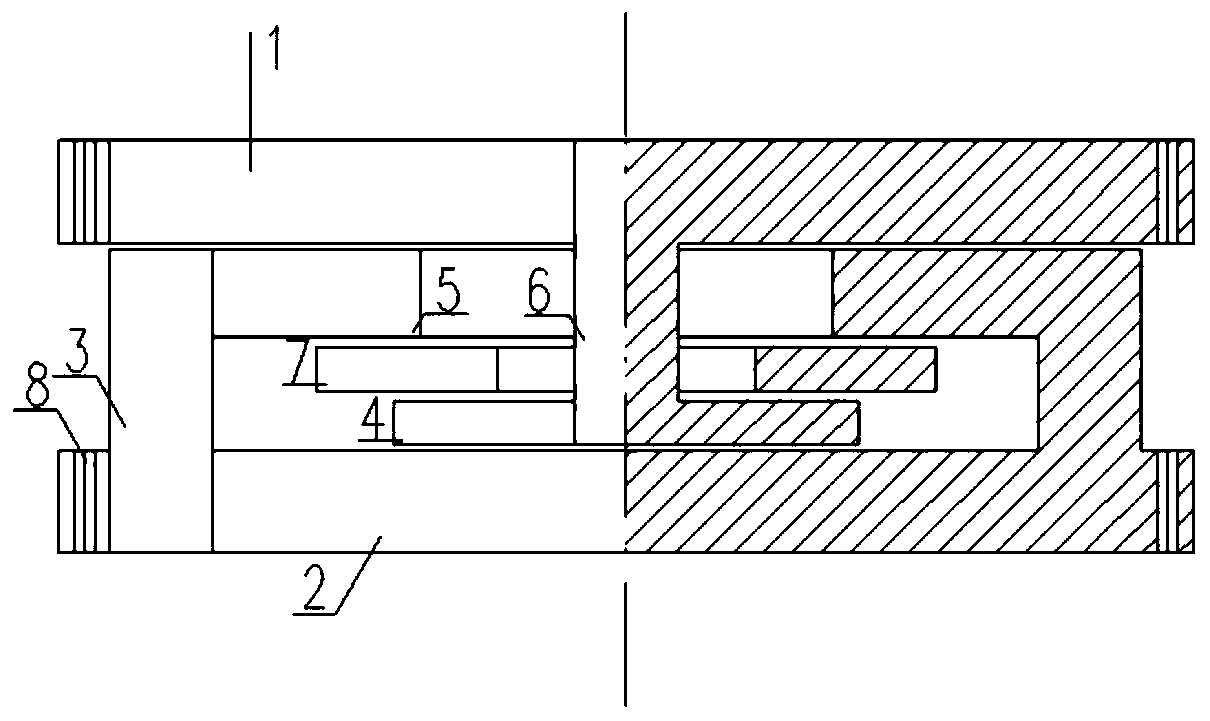
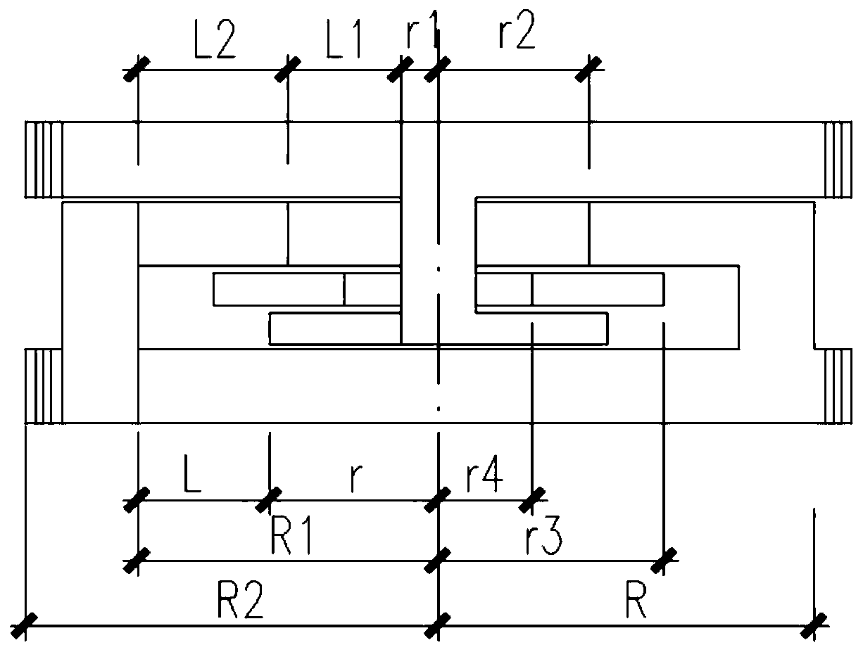
[0054] like figure 1 , figure 2 , Figure 4 , Figure 5 , Image 6 As shown, the upper mobile body 1 and the lower supporting mobile body support have connection holes connected with external objects. Figure 4 It is a schematic diagram of the movement of Example 1 of the present invention under the action of external force; Figure 5 It is a schematic diagram of the displacement of Embodiment 1 of the present invention along the direction perpendicular to the moving direction under the action of external force, or the displacement control amount along the direction perpendicular to the moving direction. Image 6 It is a schematic diagram of the structure of embodiment 1 when it is inverted, and other components are also inverted correspondingly at this time. Figure 8 , Figure 9 , Figure 10 is a top view of the structural member. Figure 9 The middle anti-disengagement connector 6 and the lower anti-disengagement moving body 4 are integral components. like figu...

Embodiment 2

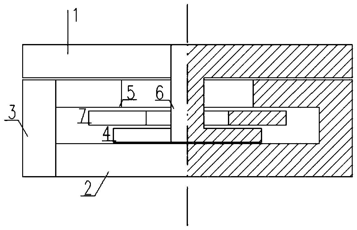
[0065] like image 3 , Figure 7 As shown, between the upper moving plate 1 and the lower supporting moving body 2, the lower supporting moving body 2 is connected with a controlled moving block 3 and an upper anti-disengagement controlled moving body 5, and the upper moving body 1 is connected with an anti-disengagement connector 6 and The lower anti-separation moving body 4 and the middle anti-separation connecting piece 6 pass through the upper anti-separation control moving body 5 and the anti-separation plate 7. One end of the control mobile blocking body 3 is connected with the lower support mobile body 2, and one end is connected with the upper anti-disengagement control mobile body 5, and supports the upper mobile body 1. Figure 7 It is a schematic diagram of the movement of Example 2 of the present invention under the action of external force.


PUM


Abstract

The invention provides a movable anti-disengagement support. A control moving block is a hollow column, the lower end of the control moving block is fixedly connected with a lower support moving body, and the upper end of the control moving block is fixedly connected with an upper anti-disengagement control moving body; the upper anti-disengagement control moving body is of an annular structure; a lower anti-disengagement moving body is of a disc structure and is located in a cavity formed by a lower support moving body, the control moving block and the upper anti-disengagement control moving body; an anti-disengagement plate is of an annular structure and located between the lower anti-disengagement moving body and the upper anti-disengagement control moving body, the outer diameter of the anti-disengagement plate is larger than the inner diameter of the upper anti-disengagement control moving body, and the inner diameter of the anti-disengagement plate is smaller than the outer diameter of the lower anti-disengagement moving body; an anti-disengagement connecting part is of a column structure, the upper end of the anti-disengagement connecting part is fixedly connected with the lower surface of an upper moving body, and the lower end of the anti-disengagement connecting part penetrates through inner holes of the upper anti-disengagement control moving body and the anti-disengagement plate to be fixedly connected with the upper surface of the lower anti-disengagement moving body. According to the movable anti-disengagement support, disengagement does not occur in the moving process; movement inconsistent with the moving direction can be limited, and the stability of movement is improved; the amount of movement is limited, and the structure function is definite.

Description

technical field [0001] The invention relates to a support device, in particular to a sliding support device. Background technique [0002] Support devices are widely used in building structures, machinery, transportation and other fields, including mobile anti-separation supports suitable for building structures and machinery, suitable for road and railway bridge supports, and suitable for active and passive control of aviation and aerospace equipment Supports, and passive control supports for pipes and lines. [0003] Among the known mobile bearings, the commonly used structural forms include core block friction sliding bearings (such as Figure 11 shown), adjustable friction sliding bearing (such as Figure 12 shown) and straight-sliding friction sliding bearings (such as Figure 13 shown). These friction sliding bearings have their own advantages, but also have the following disadvantages and problems: [0004] 1. Under the action of external force perpendicular to th...

Claims


Application Information

Patent Timeline
Patent Type & Authority Patents(China)
IPC IPC(8): E01D19/04E04B1/36E04H9/02F16M5/00F16L3/00F16F7/08
CPCE01D19/042E01D19/046E04B1/36E04H9/021E04H9/022F16F7/08F16L3/00F16M5/00
Inventor 税浩旭税洋杨莉
Owner 税浩旭
Learn More