Side span cast-in-place section construction structure based on hanging basket and truss-type guide beam and construction method

A construction method and truss-type technology, which is applied in the direction of erecting/assembling bridges, bridges, bridge construction, etc., can solve the problems of high difficulty coefficient of construction platform, high risk of erecting supports, and unbalanced force on side piers, so as to avoid foundation Difficult to handle, easy to popularize and use, and reduce weight

Inactive Publication Date: 2017-05-31
中铁二十局集团第五工程有限公司
View PDF5 Cites 5 Cited by
  • Summary
  • Abstract
  • Description
  • Claims
  • Application Information

AI Technical Summary

Problems solved by technology

During construction, a bracket must be erected, and the beam body of this section shall be constructed on it. After the closing section is completed, the beam body of each section shall form a whole before the bracket can be removed. The following disadvantages exist in the construction of the bracket method: 1. When the side span When the cast-in-place section is higher than the ground, it is dangerous to erect the support, and more materials are used, which increases the construction cost; For balance, it is necessary to counterweight on the other side or add a pull-down device, which increases the difficulty of construction; 3. If the side span is on a hillside with poor terrain, the excavation area is large and the damage to the ground surface is large. At the same time, the construction platform is difficult to construct Big

Method used


Image

  • Side span cast-in-place section construction structure based on hanging basket and truss-type guide beam and construction method
  • Side span cast-in-place section construction structure based on hanging basket and truss-type guide beam and construction method
  • Side span cast-in-place section construction structure based on hanging basket and truss-type guide beam and construction method

Examples


Embodiment Construction

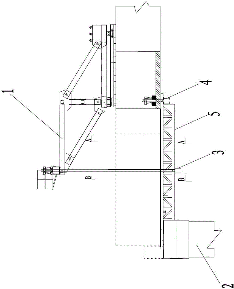
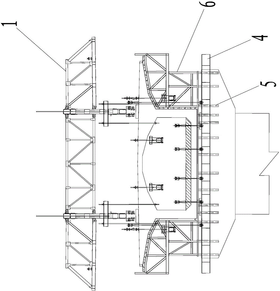
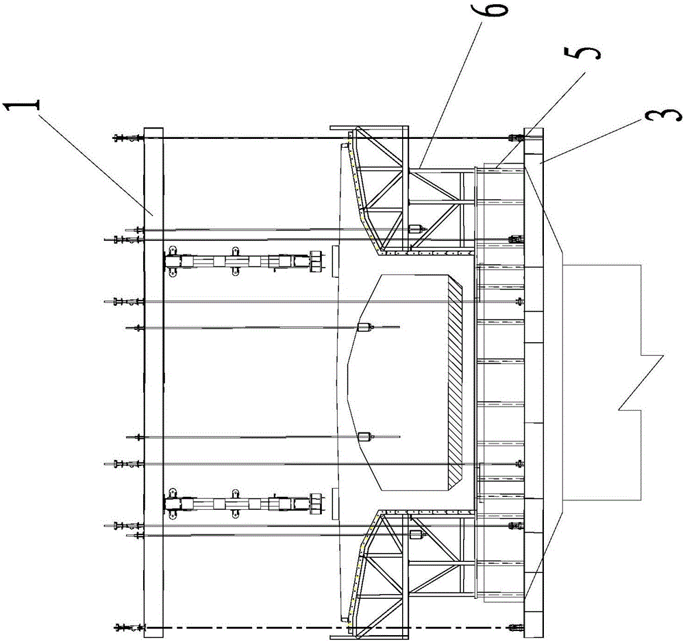
[0066] Such as figure 1 , figure 2 and image 3 As shown, the side-span cast-in-place section construction structure based on the hanging basket and the truss-type guide beam of the present invention includes the hanging basket 1, the rear crossbeam 4 of the hanging basket, and the front crossbeam of the hanging basket located below the rear crossbeam 4 of the hanging basket 3. The truss type guide beam system 5 erected on the front beam 3 of the hanging basket and the rear beam 4 of the hanging basket, and the side formwork systems 6 arranged on both sides above the truss type guide beam system 5, as well as the preloading system and balance counterweight system;

[0067] Such as Figure 4 As shown, the truss-type guide beam system 5 includes multiple unit trusses 5-1 and a bottom form 5-2 arranged above the unit trusses 5-1, and multiple unit trusses 5-1 are arranged side by side. The unit truss 5-1 includes an upper chord 5-1-1 and a lower chord 5-1-2, and a web connec...


PUM


Abstract

The invention discloses a side span cast-in-place section construction structure based on a hanging basket and a truss-type guide beam and a construction method. The construction structure comprises the hanging basket, a hanging basket front cross beam, a hanging basket rear cross beam, a truss-type guide beam system, a side formwork system, a pre-ballasting system and a balance weight system; the truss-type guide beam system comprises unit trusses and a bottom formwork arranged above the unit trusses, each unit truss comprises an upper chord member, a lower chord member and a connecting web member, each connecting web member is composed of multiple vertical web members and oblique web members, and one vertical web member is arranged between each two corresponding adjacent oblique web members; the bottom formwork comprises multiple main distribution beams crossing above the unit trusses, a square timber is arranged between each two adjacent main distribution beams, and bamboo plywood is paved above the square timbers and the main distribution beams. Through the construction structure, the technical problems of low safety, high construction difficulty coefficient when encountering poor terrain, long construction period and high construction cost caused by a support method are effectively avoided.

Description

technical field [0001] The invention belongs to the construction field of continuous rigid frame bridges, and in particular relates to a side-span cast-in-place section construction structure and construction method based on hanging baskets and truss-type guide beams. Background technique [0002] The beam body of a continuous rigid frame bridge is divided according to the construction site, including the cast-in-place section at the top of the pier, the cast-in-place section at the top of the pier, the cast-in-place section at the side span, and the closing section. Hanging baskets are installed on the pouring section, and the cantilever section is constructed with symmetrical cantilever. Before the construction of the cantilever section is completed, the construction of the side span cantilever section is completed, and finally the closing section is constructed. The side-span cast-in-place section is a part of the beam structure and is located at both ends of the continuo...

Claims


Application Information

Patent Timeline
Patent Type & Authority Applications(China)
IPC IPC(8): E01D21/10
CPCE01D21/105
Inventor 史志强胡健王相朱斌周向涛
Owner 中铁二十局集团第五工程有限公司
Why Eureka
Try Eureka