
Three-direction variable type heavy machine tool foundation model box controllable in boundary condition

A foundation model and heavy-duty machine tool technology, which is applied in basic structure engineering, basic structure testing, construction, etc., can solve the problems of inability to change its size, difficulty in adjusting soil pressure, low utilization rate, etc., and achieves convenient locking and saving. Time, easy to adjust effect

Active Publication Date: 2017-05-31
BEIJING UNIV OF TECH
View PDF6 Cites 0 Cited by
  • Summary
  • Abstract
  • Description
  • Claims
  • Application Information

AI Technical Summary

Problems solved by technology

The size of the soil box is generally a fixed shape, and its size cannot be changed after processing. It is difficult to adjust the pressure between the soil layers in the model box in the test; at the same time, the size of the model box in the test is based on the actual situation of the test bench and the structure size of the upper machine tool, The shape and other factors determine the size and shape of the model box. The current test plan is designed for the size and shape of a machine tool. For different machine tools, multiple model boxes need to be designed repeatedly, and the utilization rate is relatively low.

Method used


Image

  • Three-direction variable type heavy machine tool foundation model box controllable in boundary condition
  • Three-direction variable type heavy machine tool foundation model box controllable in boundary condition
  • Three-direction variable type heavy machine tool foundation model box controllable in boundary condition

Examples


Embodiment Construction

[0026] The present invention will be described in detail below in conjunction with the accompanying drawings.

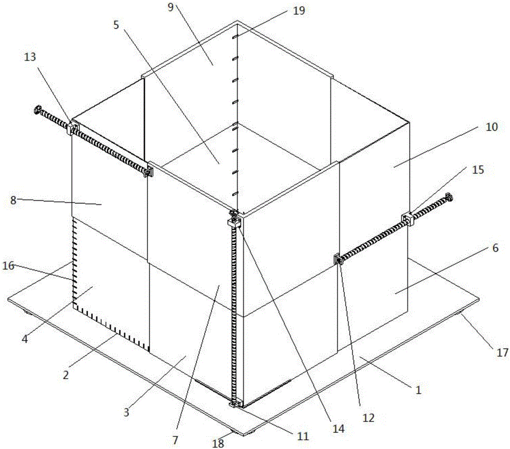
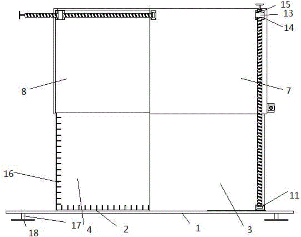
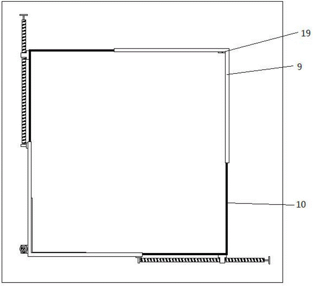
[0027] Such as Figure 1-Figure 10 Shown is a three-way variable model box device. In the figure, bottom plate 1, leak-proof strip 2, lower baffle A3, lower baffle B4, lower baffle C5, lower baffle D6, upper baffle E7, upper baffle F8, upper baffle G9, upper baffle H10, bearing base 11, bearing 12, ball screw lifter 13, bolt groove 14, bolt 15, scale 16, displacement sensor 17, horizontal knob 18, pressure sensor 19. The leak-proof strip 2 just covers the gap between the bottom plate and each baffle; the lower baffle A3, the lower baffle B4, the lower baffle C5, and the lower baffle D6 are horizontally inserted into each other; the upper baffle E7, the upper baffle F8, the upper baffle The baffle G9 and the upper baffle H10 are inserted into each other horizontally and vertically inserted into the lower baffle A3, the lower baffle B4, the lower baffle C5, and the lo...


PUM


Abstract

A three-direction variable type heavy machine tool foundation model box controllable in boundary condition comprises a bottom plate, leakage-proof strips, a lower baffle A, a lower baffle B, a lower baffle C, a lower baffle D, an upper baffle E, an upper baffle F, an upper baffle G, an upper baffle H, bearing bases, bearings, ball screw lifters, bolt grooves, bolts, calibrated scales, displacement sensors, horizontal rotary knobs and pressure sensors. The lower baffle A is clamped on the bottom plate. Three ball screws adjust the lengths in the x, y and z directions correspondingly according to data of the pressure sensors, and the pressure between different soil layers in an experiment is adjusted. The bearing bases and the ball screw lifters are fixed to the baffles through screws. The friction force between the ball screws and the bearing bases is reduced through the bearings. The displacement sensors are used for detecting whether the model box is horizontal or not and are adjusted through the horizontal rotary knobs. The pressure sensors facilitate detecting of the pressure between all the soil layers, are used for controlling the artificial boundary conditions and adjusting the artificial boundary conditions according to an experimental scheme, and improve the experimental precision.

Description

technical field [0001] The invention relates to the field of machine tool foundation research, in particular to the design of a model box in the machine tool foundation model test. Background technique [0002] Heavy-duty CNC machine tools are mainly used for processing large and extra-large precision parts. Industrial pillar industries and national key engineering project services. However, in order to meet the precision requirements of heavy CNC machine tools, the load-bearing capacity of the foundation is crucial. Studying the load bearing of machine tools requires building models of machine tools and foundations, followed by extensive testing using soil box tests. [0003] The soil box in the soil box test is under the pressure of the soil, and the soil pressure affects the artificial boundary conditions of the foundation of the heavy-duty CNC machine tool. The artificial boundary conditions have a great influence on the accuracy of the soil box experiment. The soil bo...

Claims


Application Information

Patent Timeline
IPC IPC(8): E02D33/00
CPCE02D33/00
Inventor 杨聪彬周阳王建华刘志峰程江丽
Owner BEIJING UNIV OF TECH
Learn More