Assembled annular rebar buckling anchoring-connection concrete shear wall structure

A concrete shear wall and prefabricated technology, applied in the direction of walls, building components, building structures, etc., can solve the problems of slow construction speed, high production cost, high energy consumption and pollution, and achieve the goal of ensuring integrity, convenient and efficient construction, high precision effect

Inactive Publication Date: 2017-05-31
黄坤坤
View PDF6 Cites 9 Cited by
  • Summary
  • Abstract
  • Description
  • Claims
  • Application Information

AI Technical Summary

Problems solved by technology

[0002] Facing the rapid development of urbanization, the demand for urban housing is increasing. With the rapid development of the housing construction market, due to the constraints of existing housing design and construction technology, it has been unable to meet the people's requirements for housing quantity and quality.
In addition, traditional housing has many problems such as slow construction speed, difficult quality control, high production cost, high energy consumption and pollution, which also seriously restricts the development process of housing industrialization.
[0003] At present, the steel bar connection methods in prefabricated concrete structures at home and abroad mainly include sleeve grouting, restraint grout anchor, sleeve extrusion and other connection methods, but these connection methods have disadvantages in terms of cost, accuracy, construction efficiency, and construction quality. , which restricts the development of prefabricated shear wall structures, so developing a connection method with high construction efficiency, low cost and guaranteed quality is the key problem to be solved urgently

Method used


Image

  • Assembled annular rebar buckling anchoring-connection concrete shear wall structure
  • Assembled annular rebar buckling anchoring-connection concrete shear wall structure
  • Assembled annular rebar buckling anchoring-connection concrete shear wall structure

Examples


Embodiment Construction

[0016] The technical solutions of the embodiments of the present invention will be clearly and completely described below with reference to the accompanying drawings of the present invention.

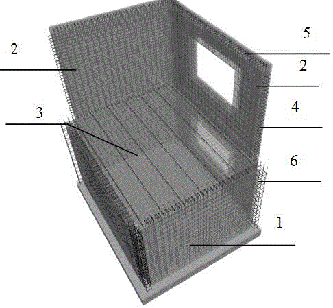
[0017] like figure 1 As shown in the figure, a prefabricated ring-reinforced anchorage concrete shear wall structure disclosed in the present invention includes an inner wall panel 1, an outer wall panel 2 and a laminated floor panel 3, wherein the inner wall panel 1 and the outer wall The plate 2 is a prefabricated annular reinforced concrete structure, and its interior is prefabricated with a horizontal annular reinforcing bar 4, a vertical annular reinforcing bar 5 and a longitudinal reinforcing bar 6 that longitudinally connects the horizontal annular reinforcing bar and the vertical annular reinforcing bar, and the superimposed floor 3 is also a prefabricated annular reinforcing bar. In the concrete structure, annular reinforcement bars (not shown in the figure) are prefabricated h...


PUM


Abstract

The invention discloses an assembled annular rebar buckling anchoring-connection concrete shear wall structure which is composed of an inner wallboard, an outer wallboard and a composite floor slab. Each of the inner wallboard and the outer wallboard is of a prefabricated annular reinforced concrete structure, horizontal annular rebars, vertical annular rebars and longitudinal rebars longitudinally connecting the horizontal annular rebars with the vertical annular rebars are prefabricated inside each prefabricated annular reinforced concrete structure, and two ends of the horizontal annular rebars extend outside left and right sides of the inner wallboard or the outer wallboard; when the inner wallboard and the outer wallboard are vertically connected with a wall, the horizontal annular rebars reserved on the left and right sides are matched with stirrups and vertical rebars and buckled in a hidden column area, and two ends of the vertical annular rebars extend outside upper and lower ends of the inner wallboard or the outer wallboard; when the inner wallboard and the outer wallboard on upper and lower layers are connected with the composite floor slab, the vertical annular rebars reserved at upper and lower ends are matched with stirrups and horizontal rebars and buckled in a hidden beam area, and then pouring is performed to form the whole shear wall structure.

Description

technical field [0001] The invention relates to a prefabricated shear wall structure, in particular to a prefabricated ring-rib buckling anchored concrete shear wall structure. Background technique [0002] In the face of the rapid development of urbanization, the demand for urban housing is increasing. While the residential construction market is developing rapidly, due to the constraints of existing housing design and construction technology, it has been unable to meet the people's requirements for the quantity and quality of housing. . In addition, traditional houses have many problems such as slow construction speed, difficult quality control, high production cost, and high energy consumption and pollution, which also seriously restrict the progress of the development of housing industrialization. [0003] At present, the connection methods of steel bars in prefabricated concrete structures at home and abroad mainly include connection methods such as sleeve grouting, re...

Claims


Application Information

Patent Timeline
Patent Type & Authority Applications(China)
IPC IPC(8): E04B1/61E04B2/64
CPCE04B1/61E04B2/64
Inventor 黄坤坤
Owner 黄坤坤
Why Eureka
Try Eureka