A segmented prestressed large-span concrete beam

A concrete beam and prestressing technology, applied in the direction of load-bearing elongated structural components, buildings, building components, etc. Effective transfer of stress and other issues, to achieve the effect of improving performance, enhancing stiffness performance, and reducing construction difficulty

Inactive Publication Date: 2019-01-04
WUHAN UNIV
View PDF2 Cites 0 Cited by
  • Summary
  • Abstract
  • Description
  • Claims
  • Application Information

AI Technical Summary

Problems solved by technology

Common prestressed concrete construction methods are pre-tensioning and post-tensioning. The construction of the tensioning end and anchoring end of this method is complex, the construction requirements are high and difficult, and prestressing can only be applied to the entire beam, which cannot be targeted The prestressing applied to the bending moment area is wasteful; the common external prestressing method is to apply prestressing to the concrete beam partially or completely by tensioning steel wires or steel rods. This method is only connected to the beam at the anchor point, so the anchorage end The concrete requirements for setting and anchoring points are relatively high, and a slight deviation will affect the effective transmission of prestress in the concrete, and the external part of the tendon is easily damaged, and even may suddenly break due to insufficient ductility during forced vibration. Happening

Method used


Image

  • A segmented prestressed large-span concrete beam
  • A segmented prestressed large-span concrete beam
  • A segmented prestressed large-span concrete beam

Examples


Embodiment Construction

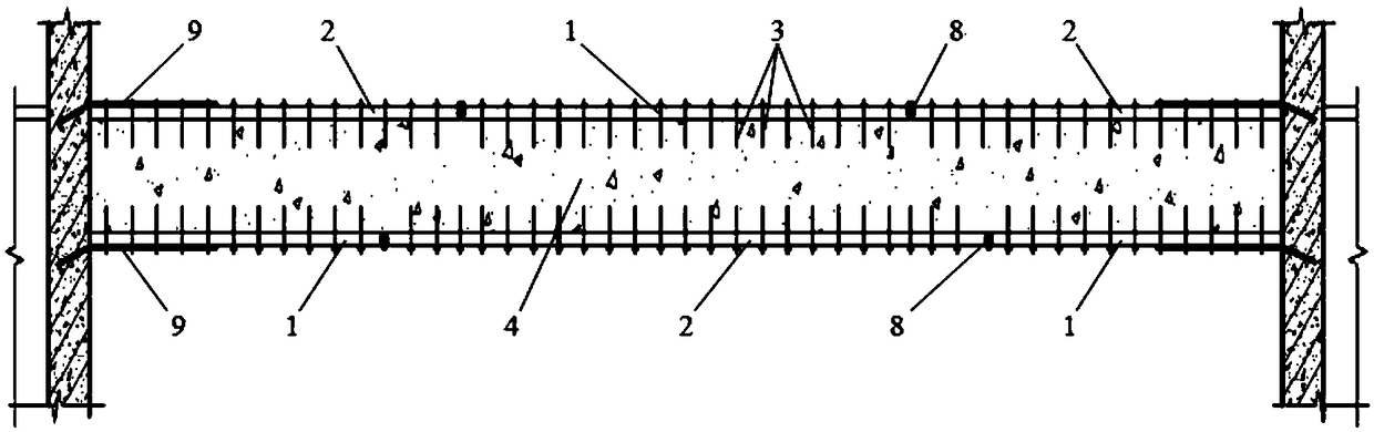
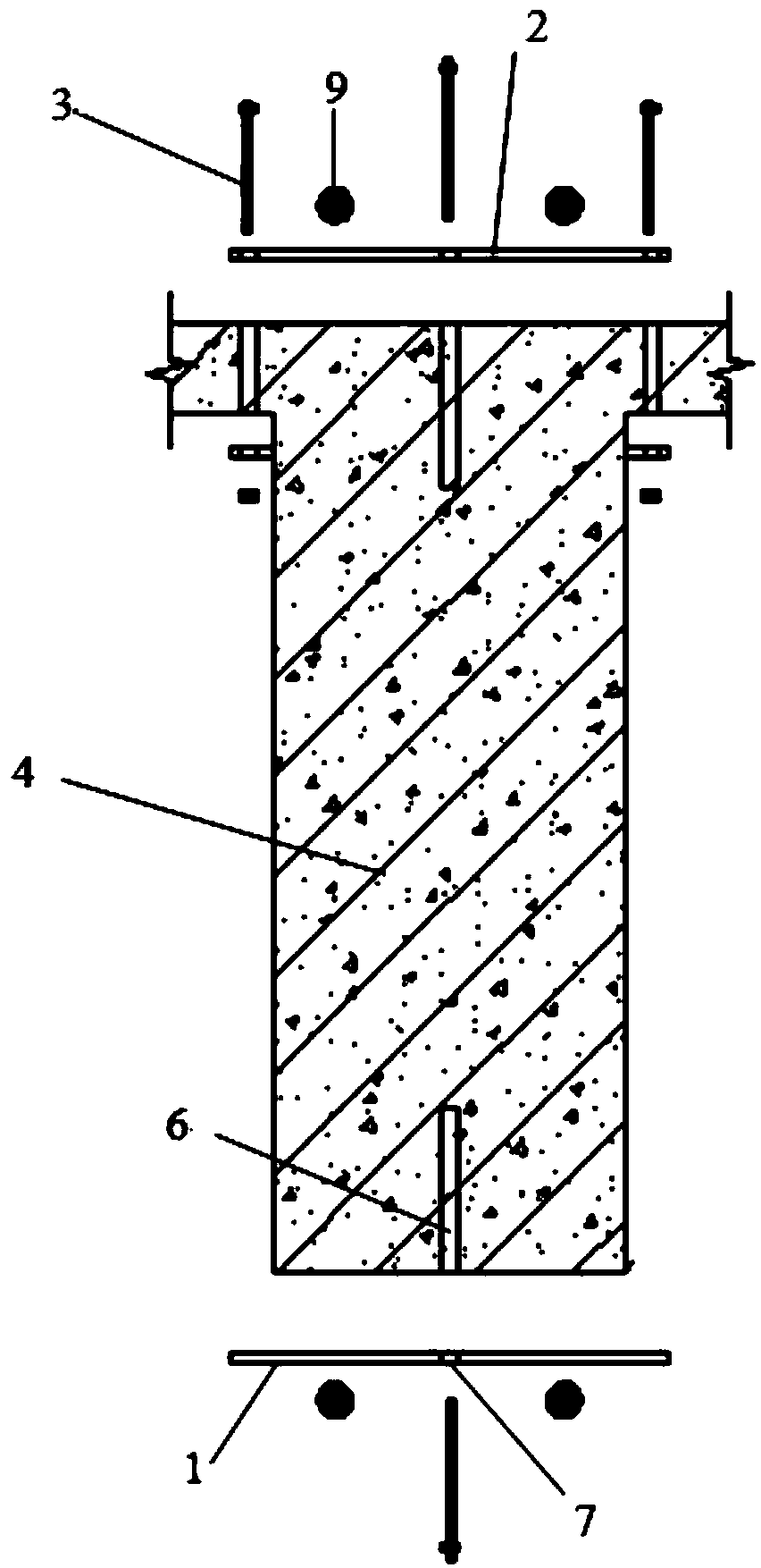
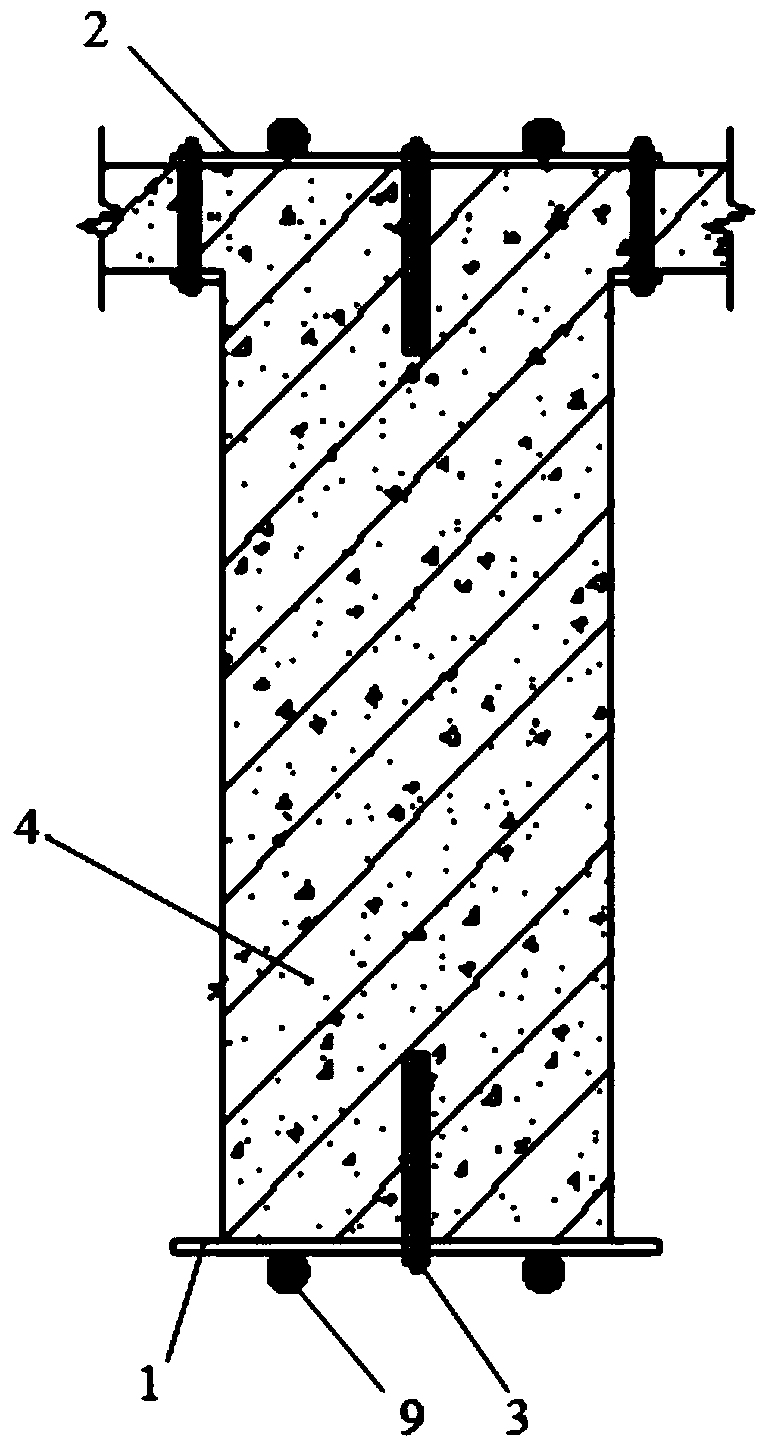
[0025] Below by embodiment, in conjunction with accompanying drawing, the technical scheme of the present invention is described further specifically, as Figure 1-7 As shown, a long-span concrete beam with prestressed sections, including a large-span concrete beam 4 in the middle and concrete columns on both sides of the beam, the upper and lower surfaces of the concrete beam 4 are laid with fixed steel plates 1 and prestressed steel plates 2. The stress steel plate 2 is located in the negative bending moment area on the upper surface of the concrete beam 4, that is, the two ends of the upper surface of the beam, and the prestressed steel plate 2 is located in the positive bending moment area on the lower surface of the concrete beam 4, that is, the middle part of the lower surface of the beam, and the upper and lower sides of the concrete beam 4 The fixed steel plate 1 is laid on other parts of the surface, and the fixed steel plate 1 and the prestressed steel plate 2 are wel...


PUM


Abstract

The invention provides a segment-prestressed large-span concrete beam which comprises a large-span concrete cross beam in the middle and concrete columns on the two sides of the cross beam. The upper surface of the concrete cross beam is paved with a fixing steel plate and prestressed steel plates, and the lower surface of the concrete cross beam is paved with fixing steel plates and a prestressed steel plate. The prestressed steel plates are separately located in the negative bending moment areas of the upper surface of the concrete cross beam and the positive bending moment area in the lower surface of the concrete cross beam. The other portions of the upper surface and the lower surface of the concrete cross beam are separately paved with the fixing steel plates. The fixing steel plates and the prestressed steel plates are welded into a whole to enable the constraining force of the prestressed steel plate to act in the full-span range of the concrete cross beam. The segment-prestressed large-span concrete beam is suitable for a large-span beam structure, and by pasting the prestressed steel plates on the surfaces of the concrete beam, the inertia moment of the transformed section of the beam is increased, and meanwhile, the inverted camber caused by prestress can counteract partial deformation, namely, the rigidity performance of the beam structure is improved; and in addition, the steel plates and bonding agents serve as protective layers of the upper surface and lower surface of concrete, and carbonization of the concrete can be reduced to an extent.

Description

technical field [0001] The invention belongs to the technical field of structural engineering in construction engineering, and in particular relates to a long-span concrete beam with segmental prestressing. Background technique [0002] With the continuous development of construction technology, buildings have higher and higher requirements for space. For example, buildings such as meeting rooms and auditoriums need to have a larger space inside. In order to meet the requirements of engineering for strength and deflection, etc. However, this method not only reduces the space used in the building, but also increases the cost of the project. At present, a better method is to use the prestressed concrete method to apply prestress in the tensile area of ​​the reinforced concrete beam, which not only increases the tensile strength of the component, but also reduces the deflection. Common prestressed concrete construction methods are pre-tensioning and post-tensioning. The constr...

Claims


Application Information

Patent Timeline
Patent Type & Authority Patents(China)
IPC IPC(8): E04C3/293E04B1/342
CPCE04B1/342E04C3/293
Inventor 赖秉洪陈尚建
Owner WUHAN UNIV
Why Eureka
Try Eureka