[0029] The technical solutions in the embodiments of the present invention will be clearly and completely described below with reference to the accompanying drawings in the embodiments of the present invention. Obviously, the described embodiments are only a part of the embodiments of the present invention, but not all of the embodiments.
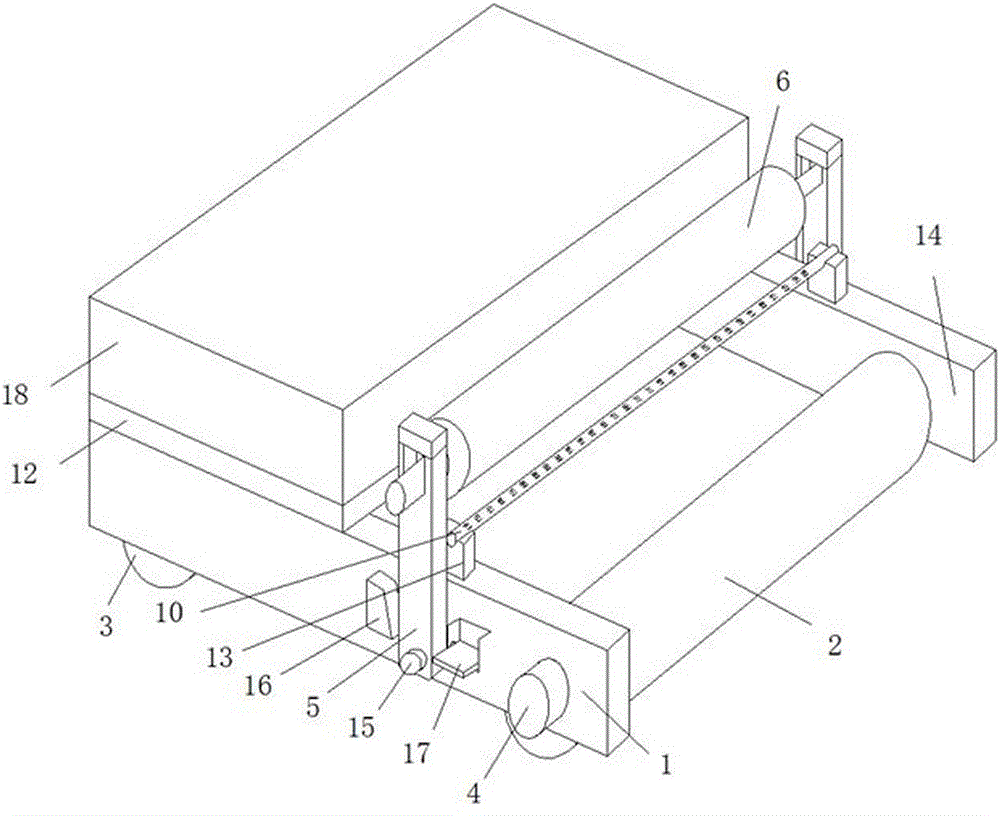
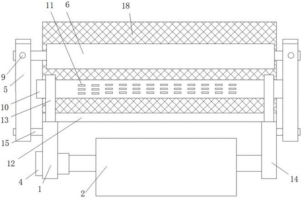
[0030] refer to Figure 1-4, Concrete film curing device, including two horizontally arranged first connecting plate 1 and second connecting plate 14, between the first connecting plate 1 and the second connecting plate 14 there is a driving roller 2 and a driven roller arranged in parallel with each other Roller 3, the driving roller 2 is placed at one end of the first connecting plate 1, the driven roller 3 is placed at the other end of the first connecting plate 1, and the outer walls of both ends of the driven roller 3 are connected to the first connecting plate 1 and the second connecting plate 1. On the opposite side wall of the connecting plate 14, the driving roller 2 is driven and connected to the driving motor 4, and the outer walls of the first connecting plate 1 and the second connecting plate 14 are symmetrically arranged with a first rotating device and a second rotating device, respectively. The first rotating device has the same structure as the second rotating device. The first rotating device includes a first support rod 5. A first limit block 16 is provided on one side of the first support rod 5. The first limit block 16 is fixedly connected to the first limit block 16. On the outer wall of the connecting plate 1, the first support rod 5 is rotatably connected to the outer wall of the first connecting plate 1. The first support rod 5 and the driving roller 2 are located on the same side of the first limit block 16, and the first support rod 5 There are first storage grooves on the outer wall of the top, and the first storage grooves are rotatably connected with the same rotating roller 6. The outer wall of the rotating roller 6 is sleeved with a protective film roller for protecting concrete. A limit through hole is provided on the upper limit, and a first limit plate 7 with a trapezoidal vertical cross-section is rotatably connected in the limit through hole, and a compression spring 8 is fixedly connected to a side wall of the first limit plate 7 away from the limit through hole. A side wall of the compression spring 8 away from the first limit plate 7 is fixedly connected with an adjustment block 9 , the outer wall of the adjustment block 9 is threadedly connected to the inner wall of the limit through hole, and the end of the adjustment block 9 away from the compression spring 8 is located at the limit Outside the through hole, a horizontally arranged object carrier 12 is arranged below the adjustment block 9 , and the bottom outer walls on both sides of the object carrier 12 are respectively fixedly connected with the top outer wall of the first connecting plate 1 and the top outer wall of the second connecting plate 14 , the top outer wall of the loading plate 12 is fixedly connected with a vertically arranged second support rod 13, the top outer wall of the second support rod 13 is rotatably connected with a ventilation pipe 10, and the outer wall of the ventilation pipe 10 is provided with a ventilation port 11, The outer wall of the ventilation pipe 10 is fixedly connected with a connecting pipe, the connecting pipe is communicated with the ventilation pipe 10, and the end of the connecting pipe away from the ventilation pipe 10 is fixedly connected with a blower, and the blower is fixedly connected to the top outer wall of the object carrier 12, and the object carrier 12 An installation box 18 is fixedly connected to the outer wall of the top of the outer wall, and the installation box 18 is provided with a trowel. The number of driven rollers 3 is two to four, and the driving roller 2 and multiple driven rollers 3 are connected with the same rubber crawler, and the design of the rubber crawler increases The contact surface between the main body of the curing device and the concrete is enlarged to prevent the curing device from leaving indentations on the concrete surface. The bottom outer wall of the first support rod 5 is provided with a horizontally arranged fixing rod 15 installation hole, and the inner wall of the fixing rod 15 installation hole is provided. A fixed rod 15 is rotatably connected, the fixed rod 15 is fixedly connected to the outer wall of the first connecting plate 1, the top outer wall of the first support rod 5 is fixedly connected with a top cover, and the side wall of the top cover is fixedly connected. A hinge is connected, the top cover is hinged with the first support rod 5 through the hinge, the outer wall of the top cover 5 is provided with fasteners, the top cover and the first support rod 5 are fixedly connected by the fasteners, and the first limit plate One side wall of 7 is inclined, and the inclined surface of the first limit plate 7 is inclined in the limit through hole. The first limit plate 7 is used to limit the position of the rotating roller 6. There is a second storage slot on the wall, the second storage slot is located between the first support rod 5 and the driving roller 2, the second storage slot is provided with a second limit block 17, and the bottom of the side wall of the second limit block 17 is A rotating rod is fixedly connected, and the rotating rod is rotatably connected to the inner wall of the second storage slot. The rotation direction of the second storage slot and the rotation direction of the first support rod 5 are at an angle of 90 degrees. The design of the second limit block 17 is convenient for the limit of the first support rod 5, so that the rotating roller 6 can be fixed firmly, and the phenomenon of tearing of the protective film due to the shaking of the equipment will not occur. The number of ventilation holes 11 is ten to thirty , the plurality of ventilation ports 11 are divided into three rows of ventilation port groups along the radial direction of the ventilation pipe 10, and the two adjacent rows of ventilation port groups form an included angle of 5 to 30 degrees, wherein the ventilation port 11 in the middle ventilation port group The air outlet direction is perpendicular to the plane formed by the straight line where the rotating shaft of the rotating roller 6 is located and the straight line where the rotating axis of the driving roller 2 is located. The design of the ventilation port 11 enables the protective film to be fully expanded before being laid on the concrete surface, so as to avoid the protective film being not fully expanded. The uneven moisture on the concrete surface leads to the problem that the local temperature of the concrete surface is too high and affects the service life of the concrete. A slider is slidably connected to the top inner wall of the installation box 18, and a cylinder is fixedly connected to the bottom outer wall of the slider, and the output end of the cylinder rotates A horizontally arranged movable block is connected, the outer wall of the movable block is fixedly connected with bolts, the output end of the cylinder is fixedly connected with the movable block, the bottom outer wall of the movable block is fixedly connected with the top outer wall of the trowel, and the side wall of the drive motor 4 is fixedly connected On the side wall of the first connecting plate 1 away from the second connecting plate 14, the side wall of the first connecting plate 1 is provided with a horizontally arranged drive motor mounting hole, and the output end of the drive motor 4 passes through the drive motor mounting hole and is fixed. Connected to the side wall of the driving roller 2, the end of the driving roller 2 away from the driving motor 4 is rotatably connected to the side wall of the second connecting plate 14, and the outer wall of the output end of the driving motor 4 is slidably connected to the inner wall of the mounting hole of the driving motor. The motor 4 is a HOL-411 type drive motor. The remote end of the drive motor 4 is connected with a controller. The controller is used to control the drive motor 4 to work. The controller is an LS-5 type universal controller. One end bypasses the driving roller 2 and is laid on the concrete surface, the driving motor 4 works, the driving roller 2 rotates and drives the equipment to move, the blower works, the air passes through the ventilation pipe 10 and is blown out from the ventilation port 11, so that the protective film is fully unfolded, which is convenient for laying. Pull the slider out from the installation box 18, the cylinder works so that the bottom surface of the trowel plate and the bottom surface of the driven roller 3 are at the same level, the concrete after the protective film is laid is directly troweled by the trowel plate, and the film coating and troweling are carried out at the same time. When replacing the protective film roller, first move the second limit block 17 into the second storage slot, open the top cover, Then move the adjustment block 9 out of the limit through hole, move the bottom of the first support rod 5 towards the ground, move the protective film roller to the outside of the first storage slot, and then screw the second limit block 17 to the second storage. In the groove, move the new protective film roller into the first storage groove, the first limit plate plays a limiting role on the protective film roller, cover the top cover, and place the first support rod 5 and the second limit The block 17 can be reset. The design of the trowel plate is convenient for the equipment to be troweled directly after laying the protective film, which avoids the need for the staff to re-trowel the work, saves time, protects the concrete in time, and improves the molding of the concrete. Quality, prolongs the service life of concrete, facilitates the protection of the film, saves time, improves work efficiency, and has a good coating effect.
[0031] Working principle: One end of the protective film on the protective film roller bypasses the driving roller 2 and is laid on the concrete surface, the driving motor 4 works, the driving roller 2 rotates and drives the equipment to move, the blower works, and the air passes through the ventilation pipe 10 and flows from the vent. 11. Blow out to make the protective film fully unfolded for easy laying. Pull the slider out of the installation box 18. The cylinder works so that the bottom surface of the trowel plate and the bottom surface of the driven roller 3 are at the same level. Flat plate smoothing, laminating and smoothing are carried out at the same time. When replacing the protective film roller, first move the second limit block 17 into the second storage slot, open the top cover, and then move the adjustment block 9 out of the limit through hole. Move the bottom of the first support rod 5 towards the ground, move the protective film roller to the outside of the first storage slot, and then screw the second limit block 17 into the second storage slot to move the new protective film roller In the first storage slot, the first limiting plate plays a limiting role on the protective film roller, cover the top cover, and reset the first support rod 5 and the second limiting block 17 .
[0032] The above description is only a preferred embodiment of the present invention, but the protection scope of the present invention is not limited to this. The equivalent replacement or change of the inventive concept thereof shall be included within the protection scope of the present invention.