Design method for landing gear buffer based on variable oil hole of oil return cavity

A technology of landing gear buffer and design method, which is applied in the directions of landing gear, shock absorber, shock absorber, etc., can solve problems such as non-variable damping, and achieve the effects of flexible design, increased power absorption, and simple and effective measures.

Active Publication Date: 2017-05-31
CHINA ACAD OF LAUNCH VEHICLE TECH
View PDF6 Cites 12 Cited by
  • Summary
  • Abstract
  • Description
  • Claims
  • Application Information

AI Technical Summary

Problems solved by technology

[0005] The purpose of the present invention is to overcome the deficiencies in the prior art and provide a design method for the landing gear buffer based on the variable oil hole in the oil return cavity. Solved the problem of realizing variable damping in the buffer that is not easy to arrange oil needles

Method used


Image

  • Design method for landing gear buffer based on variable oil hole of oil return cavity
  • Design method for landing gear buffer based on variable oil hole of oil return cavity
  • Design method for landing gear buffer based on variable oil hole of oil return cavity

Examples


Embodiment Construction

[0031] The present invention will be described in further detail below in conjunction with the accompanying drawings.

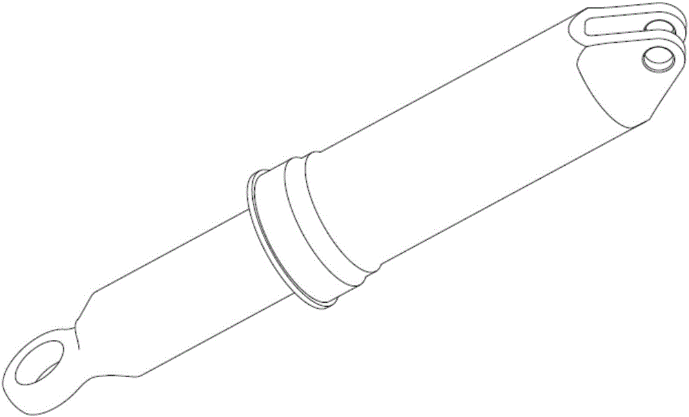
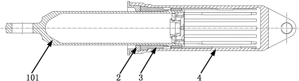
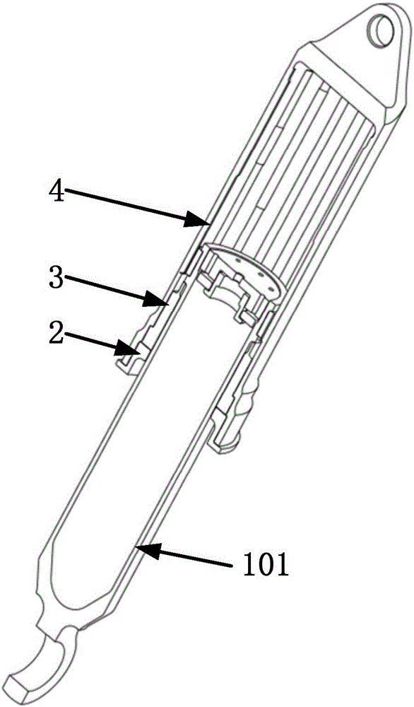
[0032] The present invention is based on the design method of the landing gear buffer of the oil return chamber and the oil change hole, see Figure 1-3 , the buffer is composed of an outer cylinder 4, a piston rod assembly 1, a lower bushing 3, and an end cover 2, the four are coaxial, a part of the piston rod assembly 1 is inside the outer cylinder 4, and a part extends out of the outer cylinder 4, and the lower The shaft sleeve 3 and the end cover 2 restrict the piston rod assembly 1 so that it cannot escape from the outer cylinder 4 . The lower shaft sleeve 3 and the end cover 2 are integrated with the outer cylinder 4 through mechanical connection.

[0033] The inside of the buffer is filled with oil and gas. When the piston rod assembly 1 is not subjected to external load, the buffer is affected by the internal gas pressure and is in a fully extended s...


PUM


Abstract

The invention relates to a design method for a landing gear buffer based on a variable oil hole of an oil return cavity. Based on an existing landing gear buffer, a plurality of penetrating grooves are uniformly formed in the outer surface of an upper support of a piston rod in the circumferential direction. A plurality of bulges corresponding to the grooves are formed in the inner surface of a buffer outer cylinder in the circumferential direction and located at the travel section of the buffer. The oil peak F1 and the air peak F2 of the existing landing gear buffer are obtained through a work quantity curve. The area An of a gap near the travel where the oil peak F1 is located is adjusted till the oil peak F1 is equal to the air peak F2. The minimum value F0 between the oil peak F1 and the air peak F2 on the work quantity curve is calculated, and if F0 is significantly smaller than F1 and F2, the area An of a gap near the travel where F0 is located is decreased. The buffer efficiency is calculated, and if the requirement is met, the sizes of the bulges on the buffer outer cylinder are determined. According to the scheme, the variable oil hole design is realized in small design space, and the design method has the preferable optimization effect on the design of efficient buffers of small aircraft landing gears.

Description

technical field [0001] The invention relates to a design method of a landing gear buffer based on an oil change hole in an oil return cavity, and belongs to the field of aircraft design. Background technique [0002] The buffer is a common part necessary for all modern landing gear, its function is to absorb the kinetic energy of the aircraft during landing and taxiing, and the degree of absorbing the kinetic energy should reduce the acceleration acting on the aircraft structure to a certain allowable level. [0003] The landing gear buffer widely used at present is the oil-pneumatic buffer. The oil-pneumatic buffer has high efficiency and good power absorption capacity: it stores energy by compressing air, and absorbs and consumes energy by controlling oil to flow through the orifice at a certain speed. [0004] During landing buffering, the buffer has different requirements for orifice damping at different compression strokes. The buffer is often equipped with a variable ...

Claims


Application Information

Patent Timeline
Patent Type & Authority Applications(China)
IPC IPC(8): F16F9/16F16F9/32B64C25/60
CPCB64C25/60F16F9/16F16F9/3221F16F9/3235
Inventor 徐方舟孔文秦王涛张庆利石小亮贾磊张晓帆苏玲姚宇地宋春雨陈亦冬姚世东王悦田甜曾凡文
Owner CHINA ACAD OF LAUNCH VEHICLE TECH
Why Eureka
Try Eureka