A variable reluctance magnetorheological damper

A magneto-rheological damper and variable reluctance technology, applied in the direction of shock absorbers, shock absorbers, springs/shock absorbers, etc., can solve the problem of strong heat generation, unstable damping characteristics of magnetorheological fluid, and restrictions on magnetic flow damping In order to reduce heat generation, light weight and low cost

Inactive Publication Date: 2018-10-12
崔葆洁 +1
View PDF5 Cites 0 Cited by
  • Summary
  • Abstract
  • Description
  • Claims
  • Application Information

AI Technical Summary

Problems solved by technology

But this method has significant disadvantages: the coil winding generates a controllable electromagnetic field by adjusting the current. Practice shows that under the same supply voltage, the current required by the electronically controlled magneto-rheological damper is already close to the corresponding torque motor. It shows that from the perspective of energy consumption, the current-controlled magnetorheological device has no advantages; secondly, studying the principle of the change of the fluid properties of the magnetorheological fluid, we found that the change of the rheological properties of the magnetorheological fluid does not depend on continuous energy input , that is to say, the magnetorheological damper is not an energy-consuming damper, so the electric energy required to maintain the electromagnetic field of the coil winding is an additional loss compared with the magnetorheological damper, and it is not a normal magnetorheological damper It is necessary for the work; third, the strong heating caused by high energy consumption also makes the damping characteristics of the magnetorheological fluid unstable, and it needs to be compensated
This restricts the popularization and application of magnetic flow dampers

Method used


Image

  • A variable reluctance magnetorheological damper
  • A variable reluctance magnetorheological damper
  • A variable reluctance magnetorheological damper

Examples


Embodiment Construction

[0025] The technical solution of the present invention will be described in detail below in conjunction with the accompanying drawings.

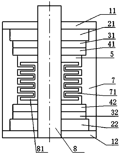
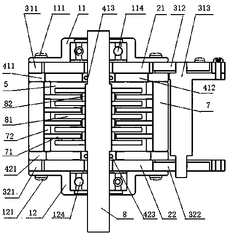
[0026] Such as figure 1 As shown, a variable reluctance magnetorheological damper according to an embodiment of the present invention includes a housing 7, an upper cover plate 11, a lower cover plate 12, an upper permanent magnet 21, a lower permanent magnet 22, a first reluctance adjustment plate 31 , second reluctance adjusting plate 32 , third reluctance adjusting plate 41 , fourth reluctance adjusting plate 42 , transmission shaft 8 , movable damping sheet group 81 and fixed damping sheet group 71 . The upper cover plate 11 is fixedly connected to the top of the housing 7, the lower cover plate 12 is fixedly connected to the bottom end of the housing 7, the two ends of the transmission shaft 8 pass through the housing 7, and are connected to the upper cover plate 11 and the lower cover plate 12 rotatable connections. The third relucta...


PUM


Abstract

The invention discloses a variable reluctance type magnetorheological damper. The damper comprises a shell, an upper cover plate, a lower cover plate, an upper permanent magnet, a lower permanent magnet, a first reluctance adjusting plate, a second reluctance adjusting plate, a third reluctance adjusting plate, a fourth reluctance adjusting plate, a transmission shaft, a movable damping fin set and a fixed damping fin set. The upper permanent magnet and the first reluctance adjusting plate are located in a first cavity and are fixedly connected. The lower permanent magnet and the second reluctance adjusting plate are located in a second cavity and are fixedly connected. The first reluctance adjusting plate and the second reluctance adjusting plate are connected through a connecting device, and rotation of the first reluctance adjusting plate and rotation of the second reluctance adjusting plate are achieved. The movable damping fin set is fixedly connected with the transmission shaft, the fixed damping fin set is fixedly connected with the shell, a first gap is formed between the movable damping fin set and the fixed damping fin set, and magnetorheological fluid is arranged in the first gap. Through the structure, the energy consumption can be reduced, heat generation is reduced, and extra radiating devices are not needed.

Description

technical field [0001] The invention relates to a magnetorheological damper, in particular to a variable reluctance magnetorheological damper. Background technique [0002] A magnetorheological damper is a device that provides motion damping. The main purpose of the magneto-rheological damper is to use damping energy consumption to reduce shock, which is widely valued in aerospace, aviation, vehicles, building anti-seismic and other industries; to use magnetorheology to generate controllable damping force, in force control technology, tactile reproduction, Robotics and other fields also have a wide range of applications. [0003] At present, magnetorheological dampers all use coil windings to generate a controllable electromagnetic field, thereby controlling the viscosity of magnetorheological fluid, and finally realizing the purpose of controllable damping of the damper. The advantage is that it can conveniently generate a controllable electromagnetic field to change the ...

Claims


Application Information

Patent Timeline
Patent Type & Authority Patents(China)
IPC IPC(8): F16F9/53F16F9/34
CPCF16F9/34F16F9/535F16F2224/045
Inventor 崔葆洁崔葆莉
Owner 崔葆洁
Why Eureka
Try Eureka